


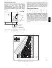
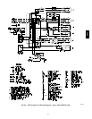

65
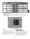
Table 29 – EconoMi$er IV Sensor Usage
APPLICATION
ECONOMI$ER IV WITH OUTDOOR AIR DRY
BULB SENSOR
Accessories Required
Outdoor Air
Dry Bulb
None. The outdoor air dry b ulb sensor is
factory installed.
Differential
Dry Bulb
CRTEMPSN002A00*
Single Enthalpy HH57AC078
Differential
Enthalpy
HH57AC078 and CRENTDIF004A00*
CO
2
for DCV
Control using a
Wall-Mounted
CO
2
Sensor
33ZCSENCO2
CO
2
for DCV
Control using a
Duct-Mounted
CO
2
Sensor
33ZCSENCO2† and
33ZCASPCO2**
O
R
CRCBDIOX005A00††
* CRENTDIF004A00 and CRTEMPSN002A00 accessories are
used on many different base units. As such, these kits may
contain p arts that will not be needed f or installation.
† 33ZCSENCO2 is an accessory CO
2
sensor.
** 33ZCASPCO2 is an accessory aspirator box required for
duct-mounted applications.
†† CRCBDIOX005A00 is an accessory that contains both
33ZCSENCO2 and 33ZCASPCO2 accessories.
3. Use the Up/Down button to select the preset
number. (See Table 28.)
4. Press Enter to lock in the selection.
5. Press Mode to exit and resume norm al operation.
The custom settings of the CO
2
sensor can be cha nged
anytime after the sensor is energized. Follow the steps
below to change the non-standard settings:
1. Press Clear and Mode buttons. Hold at least 5
seconds until the sensor enters the Edit m ode.
2. Press Mode twice. The STDSET Menu will appear.
3. Use the Up/Down button to toggle to the NONSTD
menu and press Enter.
4. Use the Up/Down button to toggle through each of
the nine variables, starting with Altitude, until the
desired setting is reached.
5. Press Mode to move through the variabl es.
6. Press Enter to lock in the selection, then press Mode
to continue to the next variable.
Dehumidification of Fresh Air with DCV (Demand
Controlled Ventilation) Control
If normal rooftop he ating and cooling operat ion is not
adequa te for the outdoor humidity level, an energy
recove ry unit and/or a dehumidification option should be
considered.
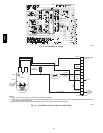
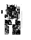
EconoMi$e r IV Pr
eparation
This procedure is used to prepare the EconoMi$er IV for
troubleshooting. No troubleshooting or testing is done by
performing the following proce dure.
NOTE: This procedure re quires a 9--v battery, 1.2
kilo--ohm resistor, and a 5.6 kilo--ohm resistor which are
not supplie d with the EconoMi$er IV.
IMPORTANT: Be sure to re cord the positions of all
potentiometers before starting troubleshooting.
1. Disconnect power at TR and TR1. All LEDs should
be off. Exhaust fan contacts should be open.
2. Disconnect device at P and P1.
3. Jumper P to P1.
4. Disconnect wires at T and T1. Place 5.6 kilo--ohm
resistor across T and T1.
5. Jumper TR to 1.
6. Jumper TR to N.
7. If connected, remove sensor from terminals SO and +.
Connect 1.2 kilo--ohm 4074EJM checkout resistor
across terminals SO and +.
8. Put 620--ohm resistor across terminals SR and +.
9. Set minimum position, DCV setpoi nt, and exhaust
potentiometers fully CCW (counterclockwise).
10. Set DCV maximum position potentiometer fully CW
(clockwise).
11. Set enthalpy potentiometer to D.
12. Apply power (24 vac) to terminals TR and TR1.
Differential
Enthalpy
To check differential enthalpy:
1. Make sure EconoMi$er IV preparati on procedure has
been performed.
2. Place 620--ohm resistor across SO and +.
3. Place 1.2 kilo--ohm resistor across SR and +. The
Free Cool LED should be lit.
4. Remove 620--ohm resistor across SO and +. The Free
Cool LED should turn off.
5. Return EconoMi$er IV settings and wiring to normal
afte r completing troubleshooting.
Single
Enthalpy
To check single enthalpy:
1. Make sure EconoMi$er IV preparati on procedure has
been performed.
2. Set the enthalpy potentiometer to A (fully CCW). The
Free Cool LED should be lit.
3. Set the enthalpy potentiometer to D (fully CW). The
Free Cool LED should turn off.
4. Return EconoMi$er IV settings and wiring to normal
afte r completing troubleshooting.
DCV (Demand Controlled Ventilation) and
Power
Exhaust
To check DCV and Power Exhaust:
1. Make sure EconoMi$er IV preparati on procedure has
been performed.
2. Ensure terminals AQ and AQ1 are open. The LED for
both DCV and Exha ust should be off. The actuator
should be fully closed.
3. Connect a 9--v battery to AQ (positive node) and AQ1
(negat ive node). The LED for both DCV and E xhaust
should turn on. The actuator should drive to between
90 and 95% open.
4. Turn the Exhaust potentiometer CW until the Exhaust
LED turns off. The LED should turn off when the
potentiometer is approximately 90%. The actuator
should remain in position.
48TC