


26
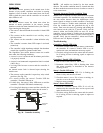
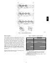
48TCDD08 only
C08238
All 48TC*D except DD08
C08239
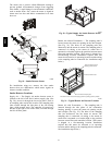
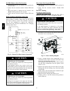
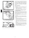
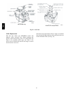
Fig. 31 -- LP Low Pressure Switch (Installed)
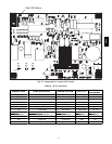
PNK
W2
TSTAT
GRA
BRN
IGC
J2-12
IGC
J2-11
BRN
C
NO
MGV
C
LP LPS
C08285
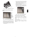
Fig. 32 -- LP Supply Line Low Pressure Switch Wiring
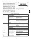
This switc h also prevents operation when the propane tank
level is low which can result in gas with a high
concentration of impurities, additives, and residues that
have settled to the bottom of the tank. Operation under
these conditions can cause harm to the heat exchanger
system. Contact your fuel supplier if this condition i s
suspected.
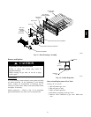
Flue Gas Passageways
To inspect the flue collector box and upper areas of the
heat exchanger:
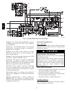
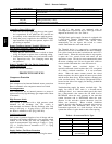
1. Remove the combustion blower wheel and motor as-
sembly according to directions in Combustion --Air
Blower section. (See Fig. 33.)
2. Remove the flue cover to inspec t the heat exchanger.
3. Clean all surfaces as required using a wire brush.
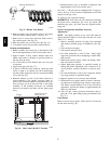
Combustion--Air Blower
Clean periodically to assure proper airflow and heating
efficiency. Inspect blower wheel every fall and
periodically during he ating season. For t he first he ating
season, inspect blower wheel bi--monthly to determine
proper cleaning frequency.
To access burner section, slide the sliding burner partition
out of the unit.
To inspect blower wheel, shine a flashlight into draft hood
opening. If cleaning is required, remove motor and wheel
as follows:
1. Slide burner access panel out.
2. Remove the 7 screws that attach induced--draft motor
housing to vestibule plate. (See Fig. 33.)
3. The blower wheel can be cleaned at this point. If ad-
ditional cleaning is required, continue with Steps 4
and 5.
4. To remove blower from the motor shaft, remove 2
setscrews.
5. To remove motor, remove the 4 screws that hold the
motor to mounting plate. Remove the motor cooling
fan by removing one setscrew. Then remove nuts that
hold mot or to mounting pla te.
6. To reinstall, reverse the procedure outlined above.
48TC