


50
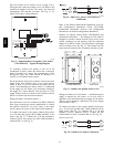
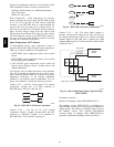
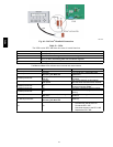
To connect the sensor to the control, identify the positive
(4 to 20 mA) and ground (SIG COM) t erminals on the
OAQ sensor. See Fig. 51. Connect the 4 to 20 mA
terminal to RTU--MP J4--5. Connect the SIG COM
terminal to RTU--MP J4 --6. (See Fig. 66.)
SEN
COM
J4-5
J4-6
OAQ Sensor/RH Sensor
24 VAC
C08463
Fig. 66 -- RTU--MP / Outdoor CO
2
Sensor
(33ZCSENCO2) Connections
On 48TC units equipped with factory--installed Smoke
Detector(s), the smoke detector controller implements the
unit shutdown through its NC contact set connected to the
unit’s LCTB input. The FSD function is initiated via the
smoke detector’s Alarm NO conta ct set. The RTU--MP
controler communicates the smoke detector’s tripped
status to the BAS building control. See Fig. 25 for unit
smoke det ector wiring.
The Fire Shut down Switch configurat ion,
MENU
Config
Inputs
input 5, identifies the
normally open status of this input when there is no fire
alarm.
Alarm state is reset when the smoke detector alarm
condition is cleared and reset at the smoke detector in the
unit.
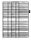
Connecting Discrete Inputs
Filter Status
The filter status accessory is a field--installed accessory.
This accessory detects plugged filters. When installing
this accessory, the unit must be configured for filter status
by setting MENU
Config
Inputs
input3,5,8,or9
to Filter Status and normally open (N/O) or normally
closed (N/C). Input 8 or 9 is recommended for easy of
installation. Refer to Fig. 60 and 61 for wire terminations
at J5.
Fan
Status
The fan status accessory is a field--installed accessory.
This accessory detects when the indoor fan is blowing air.
When installing this accessory, the unit must be
configured for fan status by setting
MENU
Config
Inputs
input3,5,8,or9to Fan
Status and normally open (N/O) or normally closed (N/C).
Input 8 or 9 is recommended for easy of installation. Refer
to Fig. 60 and 61 for wire terminations at J5.
Remote
Occupancy
The remote occupancy accessory is a field --installed
accessory. This accessory overrides the unoccupied mode
and puts the unit in occupied mode. When installing this
accessory, the unit must be configured for remote
occupancy by setting MENU
Config
Inputs
input 3,
5, 8, or 9 to Remote Occupancy and normally open (N/O)
or normal ly closed (N/C).
Also set MENU
Schedules
occupancy source to DI
on/off. Input 8 or 9 is recommended for easy of
installation. Refer to Fig. 60 and Table 21 for wire
terminations at J5.
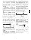
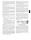
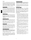
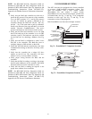
Power Exhaust (output)
Connect the accessory Power Exhaust contactor coil(s) per
Fig. 67.
Power Exhaust
J11-3
C
THERMOSTAT
PEC
TAN
GRA
LCTB
C08464
Fig. 67 -- R TU--MP Power Exhaust Connections
Space Relative Humidity Sensor -- The RH sensor is not
used with 48TC models at this time.
Communication Wiring -- Protocols
General
Protocols are the communication languages spoken by
control devi ces. The main purpose of a protocol is to
communicate information in the most efficient method
possible. Different protocols exist to provide different
kinds of information for different applications. In the BAS
application, many different protocols are used, depending
on manufacturer. Protocols do not change the function of
a controller; just make the front end user different.
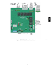
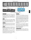
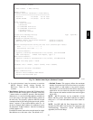
The RTU--MP can be set to communicate on four different
protocols: BACnet, Modbus, N2, and LonWorks. Switch 3
(SW3) on the board is used to set protocol and baud rate.
Switches 1 and 2 (SW1 and SW2) are used to set the
board’s network address. See Fig 68 for the switch setting
per protocol. The 3rd party connecti on to the RTU--MP is
through plug J19. Re fer to the RTU--MP 3rd Party
Integration Guide for more detailed information on
protocols, 3rd party wiring, and networking.
NOTE: Power must be cycled after changing the SW1--3
switch settings.
48TC