


25
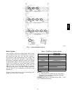
Condenser Fan Motor Protection
The condenser fan motor is internally protected against
overtemperature.
Control Circuit, 24--V
The control circui t is protec ted against overcurrent
conditions by a circuit breaker mounted on control
transformer TRAN. Reset is manual.
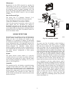
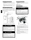
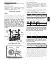
GAS HEATING SYSTEM
General
The heat exchanger system consists of a gas valve feeding
multiple inshot burners off a manifold. The burners fire
into matching primary tubes. The primary tubes discharge
into combustion plenum where gas flow converges into
secondary tubes. The secondary tubes exit into the
induced draft fan wheel inlet. The induced fan wheel
discharges into a flue passage and flue gases exit out a
flue hood on the side of the unit. The induced draft fan
motor includes a Hall Effect sensor circuit that confirms
adequate wheel speed via the Integrated Gas Control
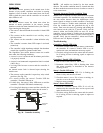
(IGC) board. Safety switches include a Rollout Switch (at
the top of the burner compartment) and a limit switch
(mounted through the fan deck, over the tubes). (See Fig.
29 and 30.)
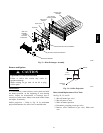
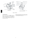
INDUCED-
DRAFT
MOTOR
MOUNTING
PLATE
BURNER
SECTION
INDUCED-
DRAFT MOTOR
MANIFOLD
PRESSURE
TAP
ROLLOUT
SWITCH
FLUE
EXHAUST
VESTIBULE
PLATE
BLOWER
HOUSING
GAS
VALVE
C09153
Fig. 29 -- Burner Section Details
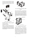
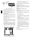
Limit Switch
and Shield
C08284
Fig. 30 -- Limit Switch Location
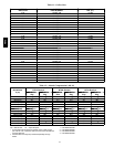
Fuel Types and Pressures
Natural Gas — The 48TC unit is fa ctory--equipped for use
with Natural Gas fuel at elevation under 2000 ft (610 m).
See section Orifice Replacement for information in
modifying this unit for installation at elevations above
2000 ft (610 m).
Gas line pressure entering the unit’s main gas valve must
be withi n specified ranges. Adjust unit gas regulator valve
as required or consult local gas utility.
Table 5 – N atural Gas Supply Line Pressure Ranges
UNIT MODEL UNIT SIZE MIN MAX
48TC All
4.0 in. wg
(996 Pa)
13.0 in. wg
(3240 Pa)
Manifold pressure is factory --adjusted for NG fuel use.
Adjust as required to obtain best flame characteristic.
Table 6 – Natural Gas Manifold Pressure Ranges
UNIT
MODEL
UNIT
SIZE
HIGH
FIRE
LOW
FIRE
RANGE
48TC All
3.5 in. wg
(872 Pa)
1.7 in. wg
(423 Pa)
2.0---5.0 in. wg (Hi)
(498---1245 Pa)
Liquid Propane — Accessory packages are available for
field--installation that will convert the 48TC unit to
operate with Liquid Propane (LP) fuels. These kits include
new orific e spuds, new springs for gas valves and a supply
line low pressure switch. See section on Orifice
Replacement for details on orifice size selections.
Fuel line pressure entering unit gas valve must remain
within specified range.
Table 7 – Liquid Propane Supply Line Pressure Ranges
UNIT MODEL UNIT SIZE MIN MAX
48TC All
11.0 in. wg
(2740 Pa)
13.0 in. wg
(3240 Pa)
Manifold pressure for LP fuel use must be adjusted to
specified range. Follow instructions in the accessory kit to
make initial readjustment.
Table 8 – Liquid Propane Manifold Pressure Ranges
UNIT MODEL UNIT SIZE HIGH FIRE LOW FIRE
48TC All
10.0 in. wg
(2490 Pa)
5.0 in. wg
(1245 Pa)
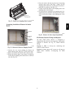
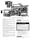
Supply Pressure Switch — The LP conversion kit includes
a supply low pressure switch. The switch contacts (from
terminal C to terminal NO) will open the gas valve power
whenever the supply line pressure drops below the
setpoint. (See Fig. 31 and 32.) If the low pressure remains
open for 15 minutes during a call for heat, the IGC circuit
will initiate a Ignition Fault (5 flashes) lockout. Reset of
the low pressure switch is automatic on rise in supply line
pressure. Reset of the IGC requires a recycle of unit
power after the low pressure switch has closed.
48TC