


57
NOTE: See RTU--MP 3rd Party Integrati on Guide (or
alternatively RTU--MP 3rd Party Integration Guide (or
alternatively RTU--MP Controls, Start--Up, Operation, and
Troubleshooting Instructions (Form 48--50H--T--2T),
Appendix) for Modbus Protocol Conformance Sta tement.
N2
1. Verify that the BAS and controller are both set to
speak the N2 protocol. The protocol of the controller
is set via SW3 (switches 3, 4, 5, and 6). The protocol
can also be verified by getting a Modstat of the
controller through t he BACview. Hit the “FN” key
and the ’.’ key at the same time to pull up a Modstat.
Scroll to the bottom of the page and there is a section
entitled ”Network Communications.” The active
protocol and baud rate will be shown in this section.
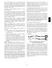
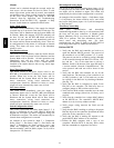
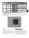
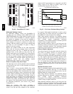
2. Verify that the BAS and controller are set for 9600
baud. The baud rate of the controller is set via SW3
(switches 1 and 2). The baud rate can also be verified
via the BACview by obtaining a Modstat. (See Fig.
70.)
3. Verify that the BAS is configured to speak 2-- wire
EIA--485 to the controller. The BAS may have to
configure jumper or DIP switches on their end.
4. Verify t hat the BAS and the controller have the same
communication settings (8 data bits, No Parity, and 1
stop bit).
5. Verify that the cont roller has a unique N2 slave
address on t he N2 bus. The control ler’s N2 slave
address is set by its rotary address switche s.
6. Verify proper wiring between the BAS and the
controller.
7. Verify that the BAS is reading or writing to the proper
network point addresses on the controller. Download
the latest points list for the controller to verify.
8. Verify that the BAS is sending his requests to the
proper slave address of our controller.
NOTE: See RTU--MP 3rd Party Integrati on Guide (or
alternatively RTU--MP 3rd Party Integration Guide (or
alternatively RTU--MP Controls, Start--Up, Operation, and
Troubleshooting Instructi ons (Form 48--50H--T--2T)
Appendix) for N2 Protocol Conformance Statement.
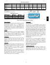
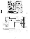
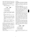
ECONOMI$ER SYSTEMS
The 48TC units may be equipped with a factory--installed
or accessory (field--installed) economizer system. Two
types are available: with a logic control system
(EconoMi$er IV) and without a control system
(EconoMi$er2, for use with external control systems such
as PremierLink). See Fig. 71 and Fig. 72 for component
locations on each type. See Fig. 73 and Fig. 74 for
economizer section wiring diagrams.
Both Ec onoMi$ers use direct--drive damper actuators.
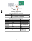
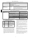
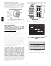
ECONOMI$ER IV
CONTROLLER
WIRING
HARNESS
ACTUATOR
(HIDDEN)
LOW TEMPERATURE
COMPRESSOR
LOCKOUT SWITCH
OUTSIDE AIR
TEMPERATURE SENSOR
(OPERATING LOCATION)
C07367
Fig. 71 -- EconoMi$er IV Component Locations
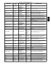
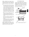
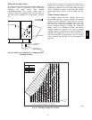
ECONOMI$ER2
PLUG
BAROMETRIC
RELIEF
DAMPER
OUTDOOR
AIR HOOD
HOOD
SHIPPING
BRACKET
GEAR DRIVEN
DAMPER
C06022
Fig. 72 -- EconoMi$er2 Component Locations
48TC