


70
UNIT OPERATION AND SAFETY HAZARD
Failure to follow this warning could result in personal
injury or death.
Disconnect gas piping from unit when leak testing at
pressure greater than 1/2 psig. Pressures greater than
1/2 psig will cause gas valve damage resulting in
hazardous condition. If gas valve is subjected to
pressure greater than 1/2 psig, it must be replaced
before use. When pressure testing field--supplied gas
piping at pressures of 1/2 psig or less, a unit connect ed
to such piping must be isolated by manually closing
the gas valve.
!
WARNING
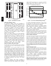
Return--Air Filters
Make sure correct filters are installed in unit (see
Appendix II -- Physical Data). Do not operate unit without
return--air filters.
Outdoor--Air Inlet Screens
Outdoor--air inlet screen must be in place before operating
unit.
Compressor Mounting
Compressors are internally spring mounted. Do not loosen
or remove compressor hold down bolts.
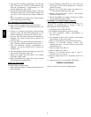
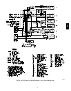
Internal Wiring
Check all factory and field electrical connections for
tightness. Tighten as required.
Refrigerant Service Ports
Each unit system has two 1/4” SAE flare (with check
valve s) service ports: one on the suction line, a nd one on
the compressor discharge line. Be sure that caps on the
ports are tight.
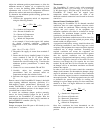
Compressor Rotation
On 3--phase units with scroll compressors, it is important
to be certain com pressor is rotating in the proper
direction. To dete rmine whether or not compressor is
rotating in the proper direction:
1. Connect service gauges to suction and discharge
pressure fittings.
2. Energize the compressor.
3. The suction pressure should drop and the discharge
pressure should rise, as is normal on any start--up.
If the suction pressure does not drop and the di scharge
pressure does not rise to normal levels:
4. Note that the evaporator fan is probably also rotating
in the wrong direction.
5. Turn off power to the unit and install lockout tag.
6. Reverse any two of the unit power leads.
7. Re --energize to the compressor. Check pressures.
The sucti on and discharge pressure levels should now
move to their normal start--up levels.
NOTE: When the compressor is rotating in the wrong
direc tion, the unit wil l make an elevated level of noise
and will not provide cooling.
Cooling
Set space thermostat to OFF position. To start unit, turn on
main power supply. Se t system selector switch at COOL
position and fan switch at AUTO. position. Adjust
thermostat to a setting approximately 5_F(3_C) below
room temperature. Both compressors start on closure of
contactors.
Check unit charge. Refer to Refrigerant Charge section.
Reset thermostat at a position above room temperature.
Both compressors will shut off. Evaporator fan will shut
off immediately.
To shut off unit, set system selector switch at OFF
position. Resetting thermostat at a position above room
temperature shuts unit off tempora r ily until space
temperature exceeds thermostat setting.
Main Burners
Main burners are factory set and should require no
adjustment.
To check ignition of main burners and heating controls,
move thermosta t setpoint above room temperature and
verify that the burners light and evaporator fan is
energized. Check heating effect, then lower the thermostat
setting below the room temperature and verify that the
burners and evaporator fan turn off.
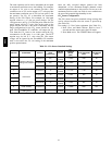
Refer to Table 11 for the correct orifice to use at high
altitudes.
Heating
1. Purge gas supply l ine of air by opening union ahead
of the gas valve. If gas odor is detected, tighten union
and wait 5 minutes before proceeding.
2. Turn on electrical supply and manual gas valve.
3. Set system switch selector at HEAT position and fan
switch at AUTO. or ON position. Set heating
temperature lever above room temperat ure.
4. The induced--draf t motor will sta rt.
5. After a call for heating, the main burners should light
within 5 seconds. If the burner does not light, the n
there is a 22--second delay before another 5--sec ond
try. If the burner still does not light, the time delay is
repea ted. If the burner does not light within 15
minutes, there is a lockout. To reset the control, break
the 24 v power to W1.
6. The evaporator--fan motor will turn on 45 seconds
afte r burner ignition.
7. The evaporator--fan motor will turn off in 45 seconds
after the thermostat temperature is satisfied.
8. Adjust airflow to obtain a temperature rise within the
range specified on the unit nameplate.
48TC