


48
Outdoor air management functions can be enhanced with
field--installation of these accessory control devices:
Enthalpy control (outdoor a ir or differential sensors)
Space CO
2
sensor
Outdoor air CO
2
sensor
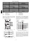
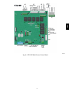
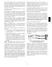
Field Connections -- Field connections for accessory
sensors and input devices are made the RTU--MP, at plugs
J1, J2, J4, J5, J11 and J20. All field control wiring that
connec ts to the RTU--MP must be routed through the
raceway built into the corner post as shown in Fig. 36.
The raceway provides the UL required clearance between
high-- and low--voltage wiring. Pass the control wires
through the hole provided in the corner post, then feed the
wires thorough the raceway to the RTU -- MP. Connect to
the wires to the removable Phoenix connectors and then
reconne ct the connectors to the board.
Space Temperature (SPT) Sensors
A field --supplied Carrier space temperature sensor is
required with the RTU-- MP to monitor space temperature.
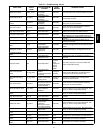
There are 3 sensors available for this application:
S 33ZCT55SPT, space temperature sensor with override
button
S 33ZCT56SPT, space temperature sensor with override
button and setpoint adjustment
S 33ZCT59SPT, space temperature sensor with LCD
(liquid crystal display) scre en, overri de button, and
setpoint adjustm ent
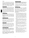
Use 20 gauge wire to connect the sensor to the controller.
The wire is suitable for distances of up to 500 ft. Use a
three--conductor shielded cable for the sensor and setpoint
adjustment connections. If the setpoint adjustment
(slidebar) is not required, then an unshielded, 18 or 20
gauge, two--conductor, twisted pair cable may be used.
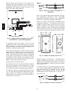
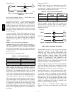
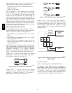
Connect T--55 — See Fig. 44 for typical T--55 internal
connec tions. Connect the T--55 SEN terminals to
RTU--MP J20--1 and J20--2. (See Fig. 62.)
SEN
SEN
J20-1
J20-2
C08460
Fig. 62 -- RTU--MP T--55 Sensor Connections
Connect T --56 — See Fig. 46 for T--56 interna l
connec tions. Install a jumper bet ween SEN and SET
terminals as illustrated. Connect T -- 56 terminals to
RTU--MP J20--1, J20--2 and J20--3 per Fig. 63.
SEN J20-1
J20-2
SEN
SET
Jumper
J20-3
SET
C08461
Fig. 63 -- RTU--MP T--56 Sensor Connections
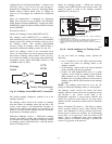
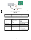
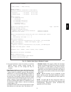
Connect T--59 — The T--59 space sensor requires a
separat e, isolat ed power supply of 24 VAC. See Fig. 64
for internal connections at the T-- 59. Connect the SEN
terminal (BLU) to RTU-- MP J20--1. Connect the COM
terminal (BRN) to J20--2. Connect the SET terminal (STO
or BLK) to J20--3.
OR SET SEN
OPB COM- PWR+
BLU (SPT)
BLK (STO)
24 VAC
SENSOR
WIRING
POWER
WIRING
BRN (COM)
NOTE: Must use a separate isolated transformer.
C07132
Fig. 64 -- Space Temperature Sensor Typical Wiring
(33ZCT59SPT)
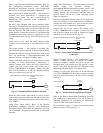
Economizer controls —
Outdoor Air Enthalpy Control (PNO HH57AC077) --
The enthalpy control (HH57AC077) is available as a
field--installed accessory to be used with the EconoMi$er2
dampe r system. The outdoor air enthalpy sensor is part of
the enthalpy control. (The separate field--installed
accessory return air enthalpy sensor (HH57AC078) is
required for differential enthalpy control. See below.)
48TC