


Variation in Maximum Airflow — As explained in
the Terminal Selection and Layout section, Moduline units
in air series can be controlled individually with a volume
controller at each unit, or with a master/slave combination,
where one controller is used with multiple units. All
the units on one controller must be of the same model
(capacity).
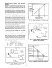
In master/slave combinations, some variation in maxi-
mum airflow among the terminals in air series will occur.
The variation in maximum airflow is a function of the unit
plenum size, the model, and the number of units in an air
series on one controller. Table 17 shows the expected varia-
tion from the unit with the smallest airflow to the unit with
the largest airflow.
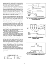
For single units with controller, the cfm variation from
the lever setting is ± 10%.
Table 17 — Multiple Unit Airflow Variation
MODEL
PLENUM
SIZE (in.)
APPROXIMATE AIRFLOW VARIATION (Cfm)
LOWEST UNIT TO HIGHEST UNIT IN AIR SERIES*
Number of Units in Air Series On
One Controller
2345
37HS1
7 x 7 10 15 20 —
9 x 9 10 15 20 25
11x1110152025
37HS2
7x7 20 — — —
9 x 9 20 30 40 —
11x11203040—
37HS4
9x9 40 — — —
11x11 40 60 — —
13x13406080—
*Values shown are based on a typical short, straight duct run be-
tween units. Variation shown may be affected if there are excessive
duct pressure losses between units.
NOTE: The variation value shown in Table 17 for a given number of
units of a certain model size (capacity) is the same for all size ple-
nums used in an air series of recommended combinations for that
model size.Thus, 3units of modelsize 37HS2, plenumsize9x9,will
have a maximum variation of 30 cfm; 3 units, plenum sizes9x9(2)
and7x7(1)will also have a maximum variation of 30 cfm. A dash
indicates that the quantity of a particular plenum size is not recom-
mended in air series for that unit size.
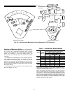
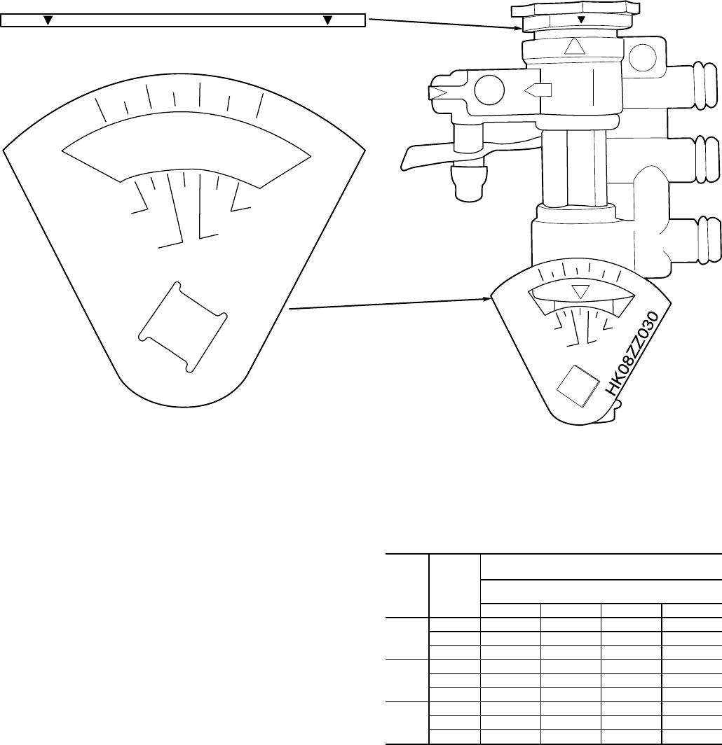
CFM
100
120
80
40
%
HK08ZZ030
MAXIMUM CFM LEVER VOLUME CONTROLLER
S
O
OPEN
MINIMUM CFM
STAR WHEEL
S
O
CFM
120
100
80
40
%
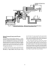
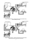
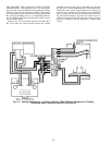
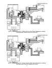
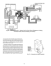
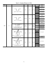
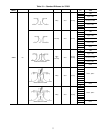
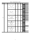
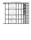
Fig. 84 — Minimum and Maximum Airflow Adjustments, 37HS Controller
72