


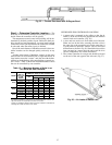
Final Layout — After these 4 steps are complete, you
are ready to make a final layout.
The final layout should show not only the number and lo-
cation of the Moduline units, but also:
• the round duct size connected to the unit
• the controller location
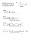
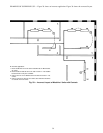
• the control tube layout for connecting the master unit (with
thermostat) to all its slaves
• the cfm for the master unit (all slaves will be the same cfm
and need not be indicated)
• the model number of the unit to be used
THE MODULINEா VALVE
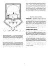
The Moduline Control Concept —
The 37HS Modu-
line system-powered control concept is based on using the
building’s primary air supply as a source of energy. The dis-
tribution duct pressure provides energy to operate the con-
trols that modulate the flow of air through the unit. The heart
of this system is a bellows-operated unit air valve, which is
positioned by varying the pressure of the air in the bellows
relative to the supply air pressure in the duct. As the pres-
sure in the bellows approaches the pressure in the supply
duct, the unit air valve opening is reduced, finally closing
completely when the pressures are equal.
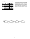
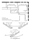
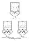
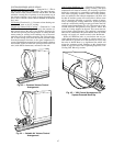
Figure 32 shows the Moduline terminal in cross section
with the valve in three positions — shutoff, partially open
and fully open. The valve opening varies with the pressure
of the bellows and the pressure of the plenum.
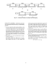
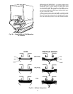
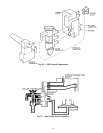
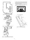
Figure 33 shows the internal components of the Moduline
unit.
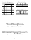
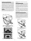
Figure 34 shows the comparison of operating character-
istics between Carrier’s new Moduline unit (the 37HS) and
the previous design.
41