


SYSTEM-POWERED APPLICATIONS
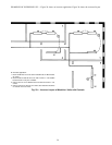
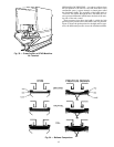
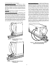
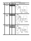
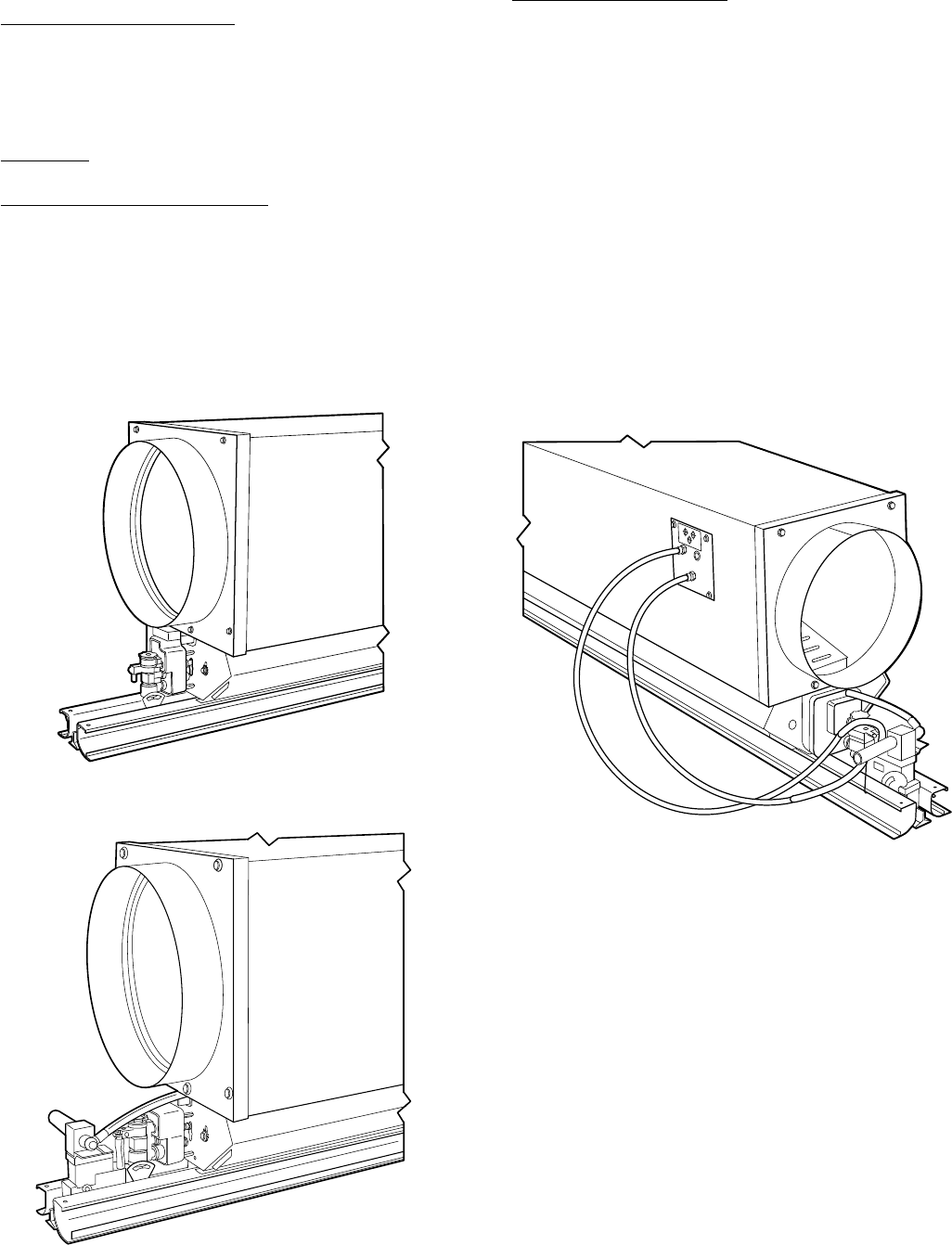
Constant Volume (CV) Cooling — (Function No. 1.) This is
the most basic operating configuration. The control arrange-
ment consists of the volume controller and the filter. The unit
maintains a steady flow of primary air at the quantity set on
the volume controller over a range of supply pressures. Fig-
ure 43 shows constant volume controls mounted on the Modu-
line unit.
CV Heating (Function No. 1.) Constant volume heating con-
trols are the same as for CV cooling.
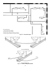
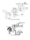
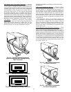
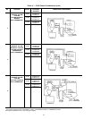
VariableAir Volume (VAV) Cooling — (Function No. 2 and
3.) The addition of a cooling thermostat to the constant vol-
ume controls allows the unit to vary the flow of primary air.
The unit will provide just enough airflow to satisfy the ther-
mostat setting at existing load conditions, up to the maxi-
mum flow set on the volume controller. The cooling thermo-
stat is direct acting (DA); thus the branch pressure output
from the thermostat increases as the space temperature in-
creases. Both diffuser-mounted and wall-mounted variations
are available. Figure 44 shows the system-powered VAV con-
trols (with diffuser thermostat) mounted on the unit.
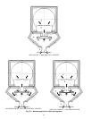
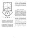
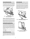
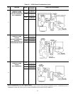
VAVCooling With Warm-Up — (Function 4.) During an ex-
tended off period (overnight or during a holiday), the space
temperature will often be lowered. It is necessary to provide
heated air, temporarily, to reestablish comfortable tempera-
tures when occupancy resumes. Since the cooling thermo-
stats are satisfied at the reduced temperature, the units will
be shut off and the system will not be able to deliver warm
air. It is necessary, therefore, to provide a means of tempo-
rarily overriding the cooling thermostat. System-powered
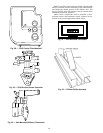
warm-up is achieved by adding a warm-up switch to the VAV
cooling control arrangement (Fig. 45). The warm-up switch,
located inside the unit plenum, closes when it senses that
warm air is being supplied to the unit. This causes the bel-
lows to bleed, opening the unit. This condition is maintained
until cool air is returned to the system and the warm-up switch,
sensing cool supply air, returns control to the thermostat.
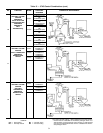
Where all Moduline units on a main duct-run are pro-
vided with thermostats for variable air volume control, it is
often difficult to get warm air to the end units on a run; with
the units in shutoff there is no significant flow which will
trigger the warm-up switch. Solutions to this situation are
found on page 58 in the Control Operating Sequences, VAV
Cooling with Warm-Up section.
Fig. 43 — Constant Volume Control
Arrangement
Fig. 44 — Variable Air Volume Control
Arrangement
Fig. 45 — VAV Control Arrangement for
System-Powered Warm-Up
47