


As a result, slightly higher maximum cfm per unit is al-
lowed as compared to interior zones or the north perimeter,
which have relatively constant loads.
The maximum cfm per unit also is affected by the desired
sound level in the room and the type of use of the space.
For example, an executive office uses low sound levels
but the furnishings generally absorb more sound so the al-
lowable cfm/unit is only slightly lower than other types of
rooms.
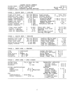
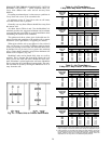
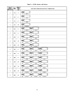
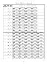
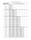
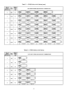
Table 3 — Recommended Maximum Cfm
Per Terminal
TYPE OF
SPACE USE
MODULINE UNITS
37HS1 37HS2 37HS4
East
West
and
South
Interior
and
North
East
West
and
South
Interior
and
North
East
West
and
South
Interior
and
North
General
Office
110 95 220 190 400 350
Private
Office
With
Carpet
100 90 200 180 330 300
With
Tile
90 80 180 160 300 270
Executive
Office
85 75 170 150 280 250
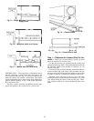
Step 2 — Lay Out Terminals
LOCATE UNITS IN T-BAR GRID — In making a layout,
begin with a plan view of the ceiling. Normally, the ceiling
grid and the lighting is done first and the diffuser plan must
fit the layout.
The center of the room is the ideal location, but where
that space has been reserved for lighting, the Moduline dif-
fuser has enough flexibility to provide good distribution when
not centered in the room.
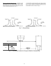
For a two-way blow diffuser, anywhere from the
1
⁄
4
point
to the
1
⁄
4
point (wall to wall) is usually suitable. Outside of
the
1
⁄
4
points, a one-way blow diffuser may be needed. Use
two-way blow diffuser wherever possible and one-way blow
only when really necessary. (See Fig. 14.)
Most jobs use a 2- x 4-ft grid T-Bar ceiling with 2- x 4-ft
or2-x2fttiles.
The first consideration in making a layout is to place the
terminals as economically as possible in the grid, which means
locating the terminals perpendicular to the main tees.
Main tees (the ones with hangers) are 4 ft on center (nor-
mally) and the cross tees are spaced 2 ft apart between the
mains to make up a 2- x 4-ft T-bar grid. Additional trim tees
may be used to divide the ceiling into a 2- x 2-ft grid.
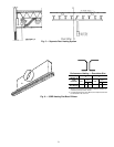
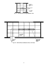
The Moduline units use mounting brackets and hang from
(run perpendicular to) the main tees. While the units can be
installed anywhere between mains, the most common loca-
tion is on the center line of the cross tee (replaces the cross
tee). The next most common location is half way between
cross tees. See Fig. 15.
While less desirable, the units can be run parallel to the
main tees. Unless absolutely necessary the units should not
replace the main tee because this means the main tee must
be cut. A location halfway between the mains is common
and in this case additional hangers are required to the upper
plenum of the unit or to the cross tee near the unit.
Special units are available for many other types of
ceilings.
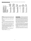
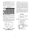
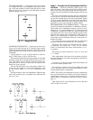
Fig. 14 — Diffuser Locations for
Preferred 2-Way or One-Way Blow
Fig. 15 — Terminal Location
25