


AIRFLOW ADJUSTMENT
Each 37HS volume controller is equipped with a maxi-
mum cfm lever for setting the required unit airflow in the
field. The lever is located at the bottom of the controller. See
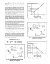
Fig. 84. The controller has a star wheel located at the top of
the controller for setting the minimum airflow. The star wheel
is also shown in Fig. 84.
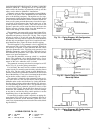
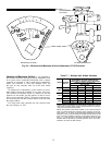
Maximum Airflow (Cfm) Adjustment — The 37HS
maximum airflow adjustment lever is common to all sizes
and is divided into levels of percent cfm. Table 16 shows the
unit airflow that will be obtained by each lever setting for
each unit size.
Table 16 — Maximum Airflow Settings
LEVER SETTING
(% CFM)
UNIT AIRFLOW (CFM)
37HS1 37HS2 37HS4
120 120 240 480
100 100 200 400
80 80 160 320
40 40 80 160
The maximum cfm is the unit airflow obtained when the
thermostat is calling for full cooling in a VAV system; it is
the design cfm for the space conditioned by the unit or units
regulated by one controller.
To set maximum cfm with zero minimum cfm:
1. Set diffuser or wall thermostat for maximum cooling.
2. Turn the minimum cfm star wheel counterlockwise until
the internal stop is reached. Do not attempt to override
stop. (Minimum cfm has been set at zero, and the unit
will turn off when required.)
3. Adjust maximum cfm lever to desired percent cfm.
Minimum Airflow (Cfm) Adjustment — Some ap-
plications require both a design maximum cfm and a mini-
mum cfm. The 37HS controller can be set to provide both
airflow requirements.
To set maximum and minimum cfm:
1. Set diffuser or wall thermostat for maximum cooling.
2. Turn the minimum cfm star wheel counterclockwise un-
til the internal stop is reached. Do not attempt to override
stop.
3. Shut off unit by adjusting thermostat to zero cool-
ing, or disconnect tube from volume controller to
thermostat.
4. Place a standard airflow hood against the outlet of the
master unit and slowly turn the minimum cfm star wheel
on the controller clockwise until the desired minimum cfm
is reached.
5. Return the thermostat to the desired setting and/or recon-
nect tube between volume controller and thermostat.
6. Adjust maximum cfm lever to desired percent cfm.
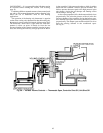
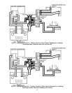
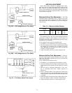
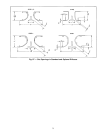
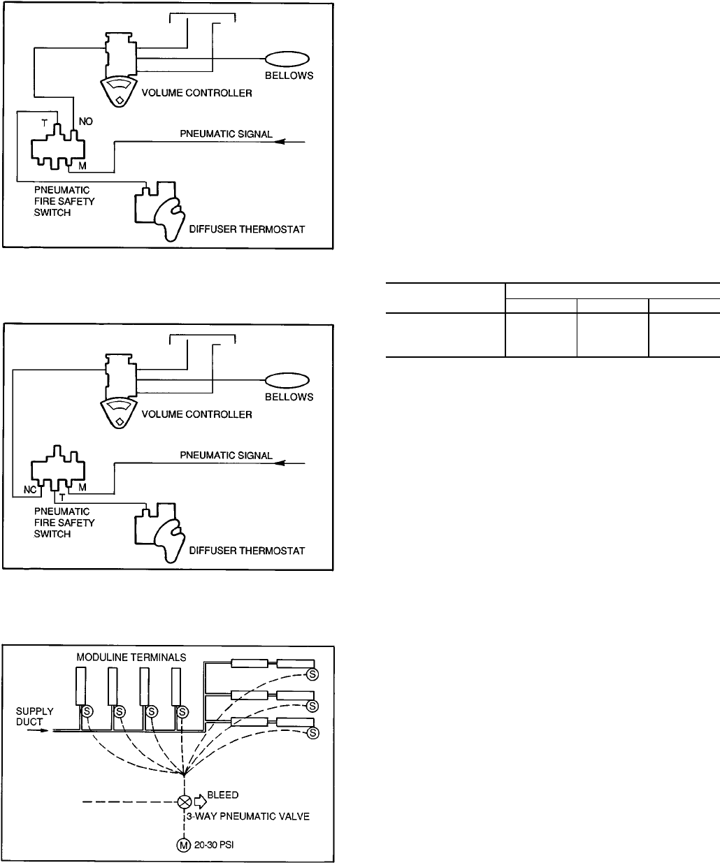
Fig. 82A — NO Configuration for Fire Safety
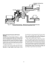
Fig. 82B — NC Configuration for Fire Safety
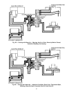
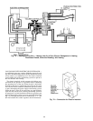
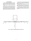
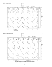
Fig. 83 — Fire Safety Switch Floor Layout
71