


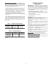
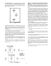
Additional Guidelines for Heating — In addition to down-
blow slot boot diffusers and Moduline director diffusers, round
nozzles spaced along the perimeter wall will also provide
satisfactory overhead heating distribution. Some guidance for
outlet use are shown in Tables 1 and 2.
Moduline heating and cooling is less flexible than sepa-
rate duct system heating with Moduline cooling because:
• Moduline heating/cooling is a changeover system requir-
ing complete replacement of the cooling duct supply air
with heated air, making zone control difficult.
• Moduline location is a compromise between obtaining out-
side wall coverage with hot air and good cooling
distribution.
Thus, separate duct heating can provide heat for a given
exposure without materially affecting the building cooling
system. The heating outlets and Moduline terminals can be
located in the most efficient air distribution places of the con-
ditioned space.
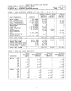
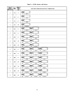
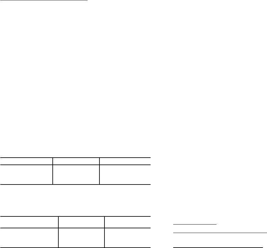
Table 1 — Optimum Outlet Discharge
DIFFUSER SLOTS VELOCITY (Fpm) TEMPERATURE (F)
Downblow slots 500 to 1250 90 to 115
Round nozzles 900 to 1800 90 to 125
One-way blow slots 600 to 2200 80 to 105
Director Diffusers 800 to 2200 90 to 105
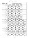
Table 2 — Location Guidelines
DIFFUSER STYLE
MINIMUM
DISTANCE (ft)*
MAXIMUM
DISTANCE (ft)*
Round Nozzles and
Downblow Slots
1.0 2.0
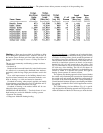
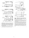
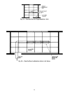
One-Way Blow Slots 0.5 L†
Director Diffusers 2.5 L†
*Feet away from outside wall.
†See Fig. 8.
TERMINAL SELECTION
AND LAYOUT
Introduction —
Selecting the terminals and making a
layout is one of the most important steps in the design pro-
cess. This is where you use your knowledge to lay out the
job at a low cost and still give your client a satisfactory job.
There are 4 items which must be considered when select-
ing an air terminal:
• air volume (Cfm) per terminal — a function of 1) the de-
sired sound level in the space, and 2) cost
• layout — a function of 1) the proper room air motion and
2) physical spacing
• unit combinations and run-out duct
• controller location
Definitions — Following are definitions of terms used
when discussing the layout of a Moduline system.
Moduline units are arranged as single units or as units in
an air series.
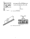
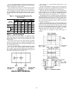
SINGLE UNIT — A single unit is connected to the supply
duct and supplies conditioned air to a space or part of a space.
Fig. 9.
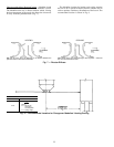
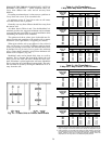
AIR SERIES — Units in air series are connected unit-to-
unit or with interconnecting ductwork and the supply air for
all units enters the first unit in the series. Fig. 10.
MASTER UNIT — A Moduline unit with controller, alone
or in air series, is a master unit. Fig. 11.
SLAVE UNIT — A unit in air series, controlled by another
unit (master unit) is a slave unit. Fig. 11.
CONTROLS — System-powered controls are installed at the
jobsite and consist of the components shown below:
Constant Volume — Filter and volume controller.
VariableVolume, Diffuser Thermostat — Filter, volume con-
troller, thermostat with aspirator.
Variable Volume, Wall Thermostat — Filter, volume con-
troller, wall thermostat.
23