


VAV COOLING WITH WARM-UP— Including the warm-
fup switch in the volume controller/thermostat circuit al-
lows the unit to deliver air when there is warm air in the duct
system, even though the cooling thermostat is satisfied by
cool space temperature.
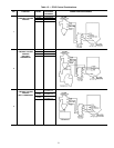
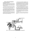
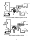
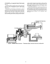
The warm-up switch is actually a temperature controlled
pneumatic valve which is normally open at primary air sup-
ply temperatures below approximately 64 F. It is installed
in-line between the volume controller and the thermostat.
When warm primary air is supplied to restore comfort con-
ditions in the space after an extended shutdown, the warm-up
switch reacts by closing (Fig. 59). This removes the ther-
mostat from the control circuit and prevents air from bleed-
ing from the low pressure chamber of the volume controller.
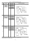
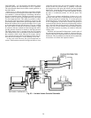
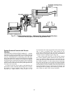
This condition simulates a thermostat calling for maximum
primary-air delivery. The unit is now, in effect, a CV unit
and operates at the set point of the volume controller. This
condition will continue as long as air in the duct system re-
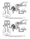
mains at a temperature higher than approximately 80 F. As
the supply air returns to normal cooling temperatures, the
switch opens and control is returned to the cooling thermo-
stat. See Fig. 60.
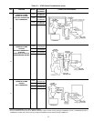
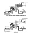
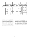
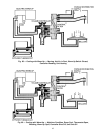
Because the units are shut off, it may be difficult to es-
tablish the flow of warm air to initiate warm-up. One method
of overcoming this problem is to install one or more CV units
near the end of the duct run. Where possible, a constant vol-
ume unit is located in space not continuously occupied such
as halls, aisles, or storage rooms. It can also be helpful in an
area benefiting from continuous circulation. By locating such
a unit at the end of a duct run, the heated air for morning
warm-up is assured of reaching the VAV units. See Fig. 61.
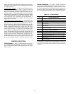
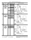
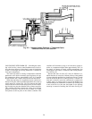
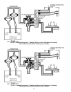
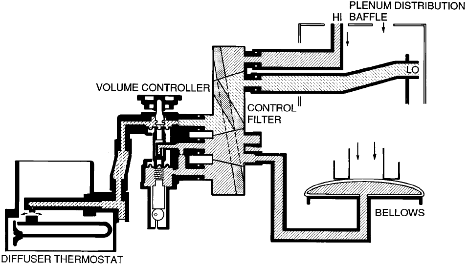
Fig. 58 — Variable Volume Controls — Thermostat Open,
Controller Shut Off, Unit Shut Off
58