


ceiling designs and building control systems. Moduline ter-
minals installed in modular ceilings can be moved easily when
tenant requirements change, and the quiet, linear slot distri-
bution integrates well in most commercial ceilings. Figure 2
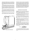
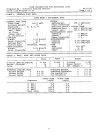
shows a 37HS Moduline unit with variable air volume (VAV)
controls.
The basic Moduline terminal control system is system pow-
ered; the distribution duct pressure provides the energy to
operate the devices that control all the units in the system.
This system can be thought of as reactive. The control reacts
to changes in occupied space conditions and to changes in
supply duct airflow and pressure, and adjusts the unit valve
to maintain preset airflow or flow proportional to the room
load.
It is also possible to apply directive controls, both pneu-
matic and electric, to the Moduline terminal. In these ap-
plications, the Moduline control system is still system pow-
ered. The difference is that now the space can be controlled
by other sensors and devices, replacing the reactive control
devices.
This application data book provides design guidance for
layout of a Moduline system. All aspects of the unit appli-
cation are included: Unit layout, control location, control
characteristics, control system options and air distribution
characteristics. This book covers both system-powered con-
trol and system-powered with electric or pneumatic inter-
face controls. Application information for Carrier’s electronic
Product Integrated Controls (PIC) can be found in a separate
publication. (Moduline units with PIC controls can be con-
trolled as part of the Carrier Comfort Network [CCN] sys-
tem.) Sound power levels and sound application data are found
in the 37HS Sound Application Data book. Specific mount-
ing and installation data is found in the 37HS Installation,
Start-Up and Service instructions or, for PIC units, in the
37HC Installation, Start-Up and Service Instructions.
BUILDING LOAD CALCULATION
Cooling —
In order to select Moduline equipment and
lay out the building air distribution system, it is first nec-
essary to calculate the building cooling and heating loads
which the Moduline terminals will offset.
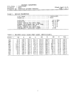
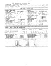
The first step is to determine the complete ‘‘block’’ load
for the building in order to size the fan, cooling equipment
and trunk duct. This estimate is for the month and hour of
greatest total building load. (See Fig. 3.)
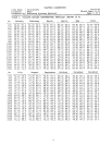
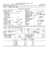
The next step is to estimate each zone load (sensible heat
only). These are used to size the terminals and run-out ducts.
The zone peak load estimates are for different months and
hours, depending on zone window orientation. (See
Fig. 4.)
These calculations are made for a building which will uti-
lize Moduline units in both perimeter and interior spaces.
The Moduline system supplies all building cooling. The heat-
ing system is described on page 20.
The object of making these load estimates is to arrive at
the required air volumes, so that the system can be designed
and equipment selected.
The airflow through a variable volume system is con-
stantly changing in response to the changes in the building
cooling loads. At any one moment the airflow to each tem-
perature control zone is determined by the room sensible heat
cooling load (RSH), the supply air temperature (T )
SA
and the room thermostat setting (T ), as shown in the fol-
R
lowing equation:
RSH
Zone cfm =
1.09* (T − T )
RSA
*1.09 is constant in this formula.
The fan airflow at the same moment is the sum of all the
zone airflow rates. (Duct leakage is assumed to be negligible
because of the high quality duct construction required by VAV
systems.)
Fig. 2 — 37HS Unit With VAV Controls
2