


CONTROL OPERATING SEQUENCES
System-Powered Controls
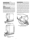
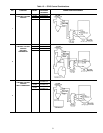
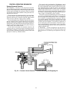
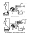
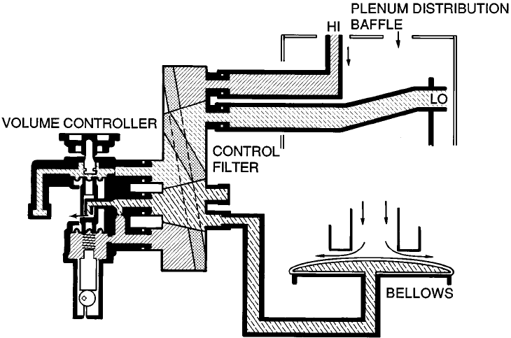
CV COOLING — See Fig. 54. Air from above the distri-
bution baffle (high pressure) enters the filter through the up-
per port of the control block, while the lower port receives
air from below the baffle (low pressure). These air streams
pass through separate filter chambers where particulate con-
taminants are removed.
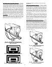
The low pressure air stream enters the low pressure cham-
ber of the volume controller from the top port of the filter,
while the bottom port of the filter feeds the high pressure
stream into the controller’s high pressure chamber.
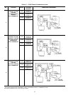
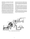
Air from the high pressure chamber feeds into the bellows
pressure chamber of the controller through the fixed orifice.
Pressure in the bellows chamber of the volume controller is
determined by the relationship between the entering flow re-
sistance of the fixed orifice and the leaving flow resistance
of the control valve variable orifice.
As the control valve opens, its resistance decreases and
relatively more air is allowed to bleed, lowering the pressure
in the bellows chamber. As the control valve closes, the ef-
fect is reversed, increasing the bellows pressure. This is the
principle of control by matched orifices.
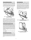
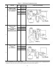
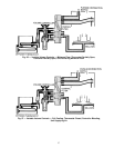
The control valve is positioned by 2 diaphragms, one in
the low pressure chamber and one in the high pressure cham-
ber, and an adjustable spring. Pressure above the low pres-
sure diaphragm tends to open the control valve while the
high pressure diaphragm tends to hold it closed. The spring
tension balances these forces as the pressures vary and de-
termines the valve position. Rotating the adjusting dial on
the volume controller changes the spring tension and pro-
vides a means of establishing a flow set point.
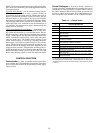
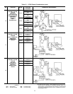
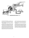
The bellows pressure determined by the action of the con-
trol valve is communicated to the bellows. As the plenum
pressure changes, the control bellows valve is constantly re-
set to maintain a corresponding bellows pressure. The bel-
lows pressure chamber of the volume controller feeds air back
through the middle port and chamber of the filter (also called
a bellows pressure chamber), to the bellows connection on
the unit end panel, and into the bellows. The bellows pres-
sure re-sets the bellows on the unit air valve to provide a
constant airflow through the unit at the value selected on the
volume controller dial.
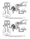
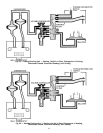
CV HEATING — Control arrangements and operation are
the same for CV heating as for CV cooling. The controls and
their operation are not affected by the temperature of the sup-
ply air.
Fig. 54 — Constant Volume Controls — Controller Bleeding, Unit Supplying Air
55