


NOTE: The following applications require the control pack-
ages shown for Function 10, plus field-supplied thermostats
as described below.
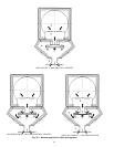
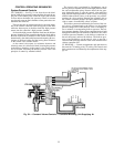
Night Set Back Heating — In the interest of energy conser-
vation, it may be desirable to raise a system’s cooling set
point during unoccupied time periods, whether they occur at
night or on weekends, holidays or other occasions. This ap-
plication requires a field-supplied dual set point DA pneu-
matic thermostat operating on a switched-main pressure supply.
The air supply must have 2 pressure levels available. A nor-
mally open pilot valve, controlled by the dual thermostat, is
also required. The thermostat set point is determined by the
supply pressure selected.
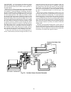
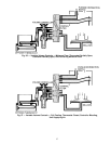
VAVCooling/Separate System Heating —A Moduline cool-
ing system may be interlocked with a separate hot water heat-
ing system and controlled by a common thermostat. This ap-
plication requires a field-supplied switched-main pressure
supply, a field-supplied dual set point DA/RApneumatic ther-
mostat, a pneumatic switching relay, a pilot valve, and a pneu-
matic hot water valve. The summer mode (cooling) or the
winter mode (heating) is selected by switching the pneu-
matic supply system pressure between high or low pressure
ranges. The pneumatic thermostat operates in either the cool-
ing mode (DA) or the heating mode (RA) depending on the
supply pressure provided. The pneumatic switching relay re-
sponds to the pressure level by selecting either the pilot valve
and the Moduline cooling system or the hot water valve and
the hot water heating system, to match the thermostat mode.
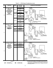
CONTROL SELECTION
Control Index —
Table 14 summarizes the control func-
tions available with 37HS Moduline air terminals. These func-
tions are described in detail in the preceding Control Appli-
cations section.
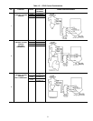
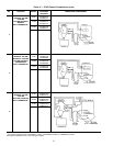
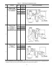
Control Packages — In order to obtain a desired set
of control functions with Moduline air terminals, the correct
combination of control packages is required. Table 15 shows
the control packages that must be installed on a master unit
in order to achieve each function. The control package num-
bers correspond to the numbers on the 37HS Price Pages.
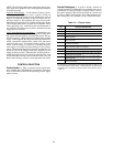
Table 14 — Control Index
FUNCTION
NO.
FUNCTION DESCRIPTION
1 Cooling or Heating Only, Constant Volume
2 Cooling Only, Variable Volume, Diffuser Thermostat
3 Cooling Only, Variable Volume, Wall Thermostat
4
VAV Cooling with System-Powered Warm-Up,
Wall Thermostat
5
VAV Cooling/Heating, System-Powered Changeover,
Wall Thermostat
6
VAV Cooling with Electric Warm-Up, Wall Thermostat
or Diffuser Thermostat
7
VAV Cooling/Heating, Electric Changeover,
Wall Thermostat or Diffuser Thermostat
8 VAV Cooling with Electric Heat Interlock
9 Heating Only, Variable Volume, Wall Thermostat
10
VAV Cooling with Pneumatic Sequenced Heating (Hot Water)
and Pneumatic Thermostat*
11
VAV Cooling with Pneumatic Warm-Up or Fire Safety Switch,
Wall Thermostat
12
VAV Cooling with Pneumatic Warm-Up or Fire Safety Switch,
Diffuser Thermostat
*For night set backheating, a field-supplied dual set point DAthermostat must
be used with the control packages and components shown in Table 15. For
VAV cooling/separate system heating, a field-supplied dual set point DA/RA
thermostat must be used with the control packages and components shown
in Table 15.
50