


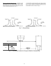
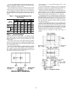
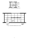
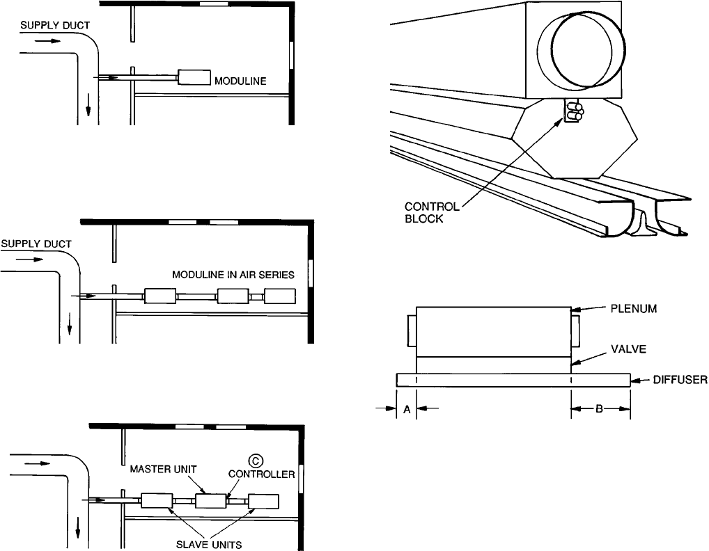
CONTROL END — The control end of a Moduline unit is
the end containing a control block at the end plate of the
valve section of the unit. (Fig. 12.) The end of the unit op-
posite the control end contains a blank block. The control
end of the Moduline unit is at the longer of the diffuser pro-
jections from the plenum. In Fig. 13, the longer projection,
B, is the control end.
The filter, volume controller, and diffuser-mounted ther-
mostat are applied to the control end of a master unit.
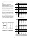
Step 1 — Determine Air Volume (Cfm) Per Ter-
minal —
Before you can start making a layout, you must
know the required air volumes (cfm).
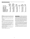
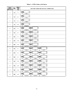
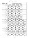
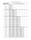
Use the cfm per zone you obtained from the cooling load
calculation and, using Table 3, Recommended Maximum Cfm
Per Terminal, decide on the number of terminals you will
need in each zone.
Cost dictates that the fewest number of Moduline units be
used consistent with good design. The maximum cfm per
unit that can be used (to keep the total number of units down)
is mainly a function of maximum acceptable sound level.
Perimeter zones with glass in the east, west, and south
building zones have peaks of rather short duration (i.e. loads
vary widely during the course of the day and year). There-
fore, a higher sound level can be tolerated for these short
peaks.
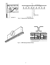
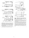
Fig. 9 — Single Modulineா Unit Connected to
Supply Duct
Fig. 10 — Moduline Units in Air Series
Fig. 11 — Master Unit and Slave Units
Fig. 12 — Control Block
Fig. 13 — Control End of Unit
24