


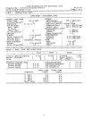

Application Data
CONTENTS
Page
INTRODUCTION ........................... 1-2
BUILDING LOAD CALCULATION .......... 2-23
Cooling ................................... 2
• LOAD CONSIDERATIONS
• DESIGN PROCEDURE
Heating ................................... 20
• OVERHEAD AIR HEATING
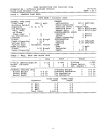
TERMINAL SELECTION AND LAYOUT ..... 23-41
Introduction ............................... 23
Definitions ................................ 23
Step 1 — Determine Air Volume (Cfm)
Per Terminal ............................. 24
Step 2 — Lay Out Terminals ............... 25
Step 3 — Consider Unit Combinations
and Run-Out Duct ........................ 27
Step 4 — Determine Controller Location .... 37
Final Layout ............................... 41
THE MODULINE VALVE ................... 41-44
The Moduline Control Concept ............. 41
• HIGH AND LOW PRESSURE
• BELLOWS PRESSURE
• UNIT AIRFLOW DELIVERY
CONTROL APPLICATIONS ................ 44-50
Introduction ............................... 44
System-Powered Controls ................. 44
• COMPONENTS OF THE SYSTEM-
POWERED CONTROL SYSTEM
• SYSTEM-POWERED APPLICATIONS
Constant Volume (CV) Cooling
CV Heating
Variable Air Volume (VAV) Cooling
VAV Cooling With Warm-Up
VAV Heating and Cooling With Changeover
VAV Heating
• SYSTEM-POWERED CONTROLS WITH
ELECTRIC INTERFACE
VAV Cooling With Electric Warm-Up
VAV Heating and Cooling With Electric Changeover
VAV Cooling With Electric Heat Interlock
• SYSTEM-POWERED CONTROLS WITH
PNEUMATIC INTERFACE
Pneumatic Sequenced Cooling/Heating (Hot Water)
VAV Cooling With Pneumatic Warm-Up
VAV Cooling With Fire Safety
Night Set Back Heating
VAV Cooling/Separate System Heating
CONTROL SELECTION ................... 50-54
Control Index ............................. 50
Control Packages ......................... 50
CONTROL OPERATING SEQUENCES ...... 55-71
System-Powered Controls ................. 55
• CV COOLING
• CV HEATING
• VAV COOLING
• VAV COOLING WITH WARM-UP
Page
• VAV HEATING AND COOLING WITH
SYSTEM-POWERED CHANGEOVER
• VAV HEATING
System-Powered Controls With
Electric Interface ......................... 64
• VAV COOLING WITH ELECTRIC WARM-UP
• VAV HEATING AND COOLING WITH
ELECTRIC CHANGEOVER
• VAV COOLING WITH ELECTRIC HEAT
INTERLOCK
System-Powered Controls With
Pneumatic Interface ...................... 69
• PNEUMATIC SEQUENCED HEATING/
COOLING (HOT WATER)
• VAV COOLING WITH PNEUMATIC
WARM-UP OR FIRE SAFETY SWITCH
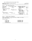
AIRFLOW ADJUSTMENT .................. 71,72
Maximum Airflow (Cfm) Adjustment ........ 71
Minimum Airflow (Cfm) Adjustment ......... 71
Variation in Maximum Airflow .............. 72
AIR DISTRIBUTION ........................ 73
Throw for Standard Diffusers ............... 82
INTRODUCTION
The Moduline air terminal (Fig. 1) is a truly flexible unit
for the control and distribution of conditioned air to the oc-
cupied space. Available in 3 airflow sizes for single or mul-
tiple terminal installation, it is adaptable to a variety of
Fig. 1 — Moduline Air Terminal
37HS
Modulineா Air Terminals
Manufacturer reserves the right to discontinue, or change at any time, specifications or designs without notice and without incurring obligations.
Book 3
Tab 6a
PC 201 Catalog No. 513-741 Printed in U.S.A. Form 37HS-1XA Pg 1 6-91 Replaces: New