


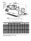
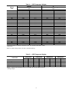
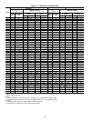
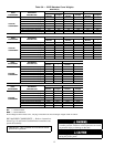
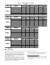
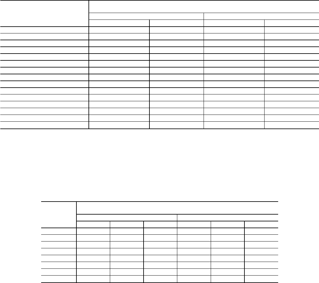
Table 2 — 19XR Dimensions (Marine Waterbox)
HEAT EXCHANGER
SIZE
A (Length, Marine Waterbox —
not shown)
2-Pass* 1 or 3 Pass†
ft-in. mm ft-in. mm
10 to 12 NA NA NA NA
15 to 17 NA NA NA NA
20 to 22 12- 6
5
⁄
8
3826 14- 3 4343
30 to 32 14- 9 4496 16- 4
3
⁄
4
4997
35 to 37 16- 5
1
⁄
2
5017 18- 1
1
⁄
4
5518
40 to 42 15- 0
1
⁄
4
4591 16- 8
3
⁄
4
5099
45 to 47 16- 8
3
⁄
4
5099 18- 5
1
⁄
4
5620
50 to 52 15- 0
1
⁄
4
4591 16- 8
3
⁄
4
5099
55 to 57 16- 8
3
⁄
4
5099 18- 5
1
⁄
4
5620
60 to 62 15- 0
3
⁄
4
4591 16- 9
1
⁄
4
5111
65 to 67 16- 9
1
⁄
4
5112 18- 5
3
⁄
4
5632
70 to 72 17- 8 5385 19-10
1
⁄
2
6058
75 to 77 19- 8 5994 21-10
1
⁄
2
6668
80 to 82 17- 8
1
⁄
2
5398 20- 1 6121
85 to 87 19- 8
1
⁄
2
6007 22- 1 6731
*Assumes both cooler and condenser nozzles on same end of chiller.
†1 or 3 pass length applies if cooler isa1or3pass design.
NOTES:
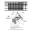
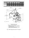
1. Service access should be provided per American Society of Heating, Refrigeration, and Air Conditioning Engineers (ASHRAE) 15, latest edition,
National Fire Protection Association (NFPA) 70, and local safety code.
2. Allow at least 3 ft (915 mm) overhead clearance for service rigging.
3. Certified drawings available upon request.
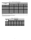
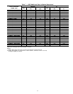
Table 3 — 19XR Nozzle Size
FRAME
SIZE
NOZZLE SIZE (in.)
(Nominal Pipe Size)
Cooler Condenser
1-Pass 2-Pass 3-Pass 1-Pass 2-Pass 3-Pass
1 866866
210 8 6 10 8 6
3 10 8 6 10 8 6
4 10 8 6 10 8 6
5 10 8 6 10 10 8
6 10 10 8 10 10 8
7 14 12 10 14 12 12
8 14 14 12 14 14 12
8