


Free-Standing, Field-Installed Starter — Assemble and in-
stall compressor terminal box in desired orientation, and cut
necessary conduit openings in conduit support plates. See
Fig. 27 and 29. Attach power leads to compressor terminals
in accordance with job wiring drawings, observing caution
label in terminal box. Use only copper conductors. The mo-
tor must be grounded in accordance with NEC (National Elec-
trical Code), applicable local codes, and job wiring diagrams.
Installer is responsible for any damage caused by improper
wiring between starter and compressor motor.
IMPORTANT: Do not insulate terminals until wiring
arrangement has been checked and approved by
Carrier start-up personnel. Also, make sure correct phas-
ing is followed for proper motor rotation.
Insulate Motor Terminals and Lead Wire Ends — Insulate
compressor motor terminals, lead wire ends, and electrical
wires to prevent moisture condensation and electrical arc-
ing. For low-voltage units (up to 600 v), obtain insulation
material from machine shipping package consisting of 3 rolls
of insulation putty and one roll of vinyl tape.
1. Insulate each terminal by wrapping with one layer of in-
sulation putty.
2. Overwrap putty with 4 layers of vinyl tape.
High Voltage Units — High-voltage units require special ter-
minal preparation. Follow local electrical codes for high-
voltage installation. Vinyl tape is not acceptable; a high voltage
terminal method must be used.
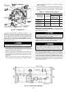
Connect Power Wires to Oil Pump Starter — See Fig. 30.
Connect power wires to oil pump starter mounted in ma-
chine power panel. Use separate fused disconnect or circuit
breaker as shown on job wiring diagrams and Fig. 30. Check
that power supply voltage agrees with oil pump voltage. Fol-
low correct phasing for proper motor rotation.
Do not punch holes or drill into the top surface of the
power panel. Knockouts are provided in the bottom of
the power panel for wiring connections.
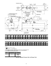
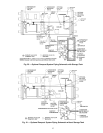
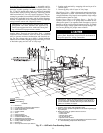
Piping
Control Wiring
Power Wiring
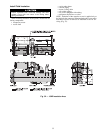
LEGEND
1—Disconnect
2—Free-Standing Compressor Motor Starter
3—Compressor Motor Terminal Box
4—Chiller Power Panel
5—Control Cabinet
6—Vents
7—Pressure Gages
8—Chilled Water Pump
9—Condenser Water Pump
10 — Chilled Water Pump Starter
11 — Condensing Water Pump Starter
12 — Cooling Tower Fan Starter
13 — Disconnect
14 — Oil Pump Disconnect (see Note 4)
IMPORTANT: Wiring and piping shown are for general point-
of-connection only and are not intended to show details for a
specific installation. Certified field wiring and dimensional dia-
grams are available on request.
NOTES:
1. All wiring must comply with applicable codes.
2. Refer to Carrier System Design Manual for details regarding pip-
ing techniques.
3. Wiring not shown for optional devices such as:
• remote start-stop
• remote alarm
• optional safety device
• 4 to 20 mA resets
• optional remote sensors
4. Oil pump disconnect may be located within the enclosure of Item
2 — Free-Standing Compressor Motor Starter.
Fig. 27 — 19XR with Free-Standing Starter
31