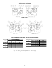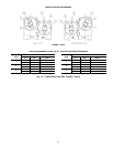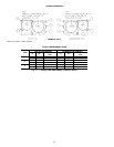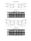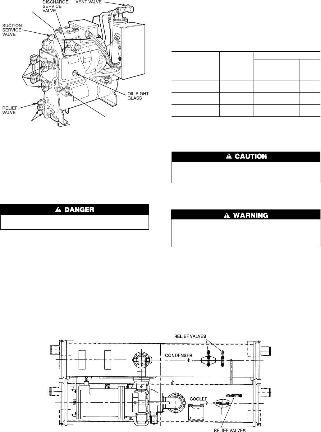
INSTALL VENT PIPING TO RELIEF VALVES — The
19XR chiller is factory equipped with relief devices on the
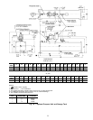
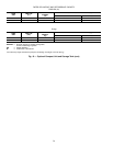
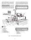
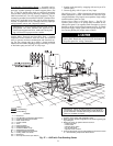
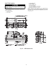
cooler and condenser shells. Refer to Fig. 23 and Table 10
for size and location of relief devices. Vent relief devices to
the outdoors in accordance with ANSI/ASHRAE 15 (latest
edition) Safety Code for Mechanical Refrigeration and all
other applicable codes.
Refrigerant discharged into confined spaces can dis-
place oxygen and cause asphyxiation.
1. If relief devices are manifolded, the cross-sectional area
of the relief pipe must at least equal the sum of the areas
required for individual relief pipes.
2. Provide a pipe plug near outlet side of each relief device
for leak testing. Provide pipe fittings that allow vent pip-
ing to be disconnected periodically for inspection of valve
mechanism.
3. Piping to relief devices must not apply stress to the
device. Adequately support piping. A length of flexible
tubing or piping near the device is essential on spring-
isolated machines.
4. Cover the outdoor vent with a rain cap and place a con-
densation drain at the low point in the vent piping to pre-
vent water build-up on the atmospheric side of the relief
device.
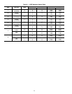
Table 10 — Relief Device Locations
RELIEF VALVE
OUTLET SIZE
LOCATION
QUANTITY
Frame 5
Compressor With
Frame 7 or 8
Heat Exchanger
All
Others
1-in. NPT FEMALE
CONNECTOR
Cooler 4 2
1-in.NPT FEMALE
CONNECTOR
Condenser 4 2
1-in. NPT FEMALE
CONNECTOR
Optional
Storage Tank
22
NOTE: All valves relieve at 185 psi (1275 kPa).
Make Electrical Connections — Field wiring must
be installed in accordance with job wiring diagrams and all
applicable electrical codes.
Do not run 120-v wiring into the control cabinet. The
control cabinet should only be used for additional extra-
low voltage wiring (50 v maximum).
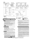
Wiring diagrams in this publication (Fig. 24-31) are for
reference only and are not intended for use during actual in-
stallation; follow job specific wiring diagrams.
Do not attempt to start compressor or oil pump (even
for a rotation check) or apply test voltage of any kind
while machine is under dehydration vacuum. Motor in-
sulation breakdown and serious damage may result.
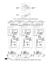
CONNECT CONTROL INPUTS — Connect the control in-
put wiring from the chilled and condenser water flow switches
to the starter terminal strip. Wiring may also be specified for
a spare safety switch, and a remote start/stop contact can be
wired to the starter terminal strip. Additional spare sensors
and Carrier Comfort Network modules may be specified as
well. These are wired to the machine control panel as indi-
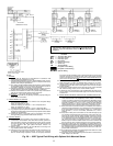
cated in Fig. 24 and 25.
CONDENSER
WATER CONNECTIONS
OIL
RETURN LINE
CONNECTION
SERVICE
VALVES
REFRIGERANT
INLET VALVE
COMPRESSOR
MOUNTING
SPRINGS
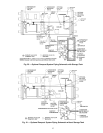
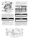
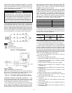
Fig. 22 — Pumpout Unit
Fig. 23 — Relief Valve Locations
28


