


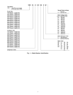
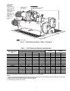
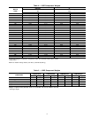
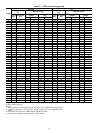
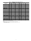
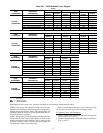
COMPRESSOR
FRAME SIZE*
COOLER
SIZE
MAXIMUM
WEIGHT (lb)
VESSEL
LENGTH
DIM. ‘‘A’’ DIM. ‘‘B’’ DIM. ‘‘C’’
CHAIN LENGTH
‘‘D’’ ‘‘E’’ ‘‘F’’
4
70-72 40,410 14Ј 6Ј-6Љ 3Ј-4Љ 3Ј-5Љ 11Ј-6Љ 12Ј-5Љ 12Ј-9Љ
75-77 44,210 16Ј 7Ј-5Љ 3Ј-5Љ 3Ј-5Љ 12Ј-0Љ 13Ј-3Љ 13Ј-6Љ
5
70-72 45,600 14Ј 6Ј-2Љ 3Ј-6Љ 3Ј-7Љ 11Ј-6Љ 12Ј-5Љ 12Ј-9Љ
75-77 49,400 16Ј 6Ј-11Љ 3Ј-6Љ 3Ј-6Љ 12Ј-0Љ 13Ј-3Љ 13Ј-6Љ
80-82 54,900 14Ј 6Ј-2Љ 3Ј-6Љ 3Ј-7Љ 11Ј-6Љ 12Ј-5Љ 12Ј-9Љ
85-87 58,300 16Ј 6Ј-11Љ 3Ј-6Љ 3Ј-6Љ 12Ј-0Љ 13Ј-3Љ 13Ј-6Љ
*The first digit of the 3-digit compressor code indicates the frame size of the compressor.
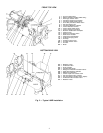
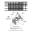
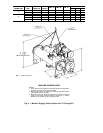
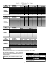
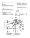
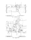
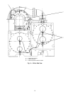
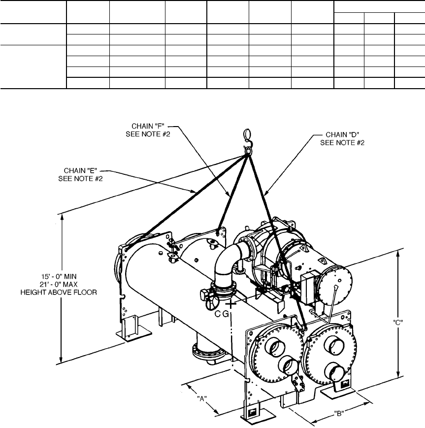
MACHINE RIGGING GUIDE
NOTES:
1. Each chain must be capable of supporting the entire weight of the
machine. See chart for maximum weights.
2. Chain lengths shown are typical for 15Ј lifting height. Some minor
adjustments may be required.
3. Dimensions ‘‘A’’ and ‘‘B’’ define distance from machine center of
gravity to tube sheet outermost surfaces. Dimension ‘‘C’’ defines
distance from machine center of gravity to floor.
Fig. 4 — Machine Rigging Guide (Cooler Size 70 Through 87)
CG — Center of Gravity
6