


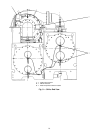
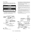
To Rig Compressor
NOTE: The motor end of the 19XR compressor is heavy
and will tip backwards unless these directions are followed:
1. Cut two 4 in. × 6 in. wooden beams to the same length
as the compressor.
2. Drill holes into the beams and bolt them to the base of
the compressor.
Additional Notes
1. Use silicon grease on new O-rings when refitting.
2. Use gasket sealant on new gaskets when refitting.
3. Cooler and condenser vessels may be rigged vertically.
Rigging should be fixed to all 4 corners of the tube sheet.
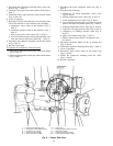
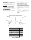
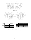
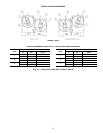
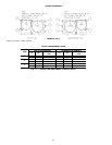
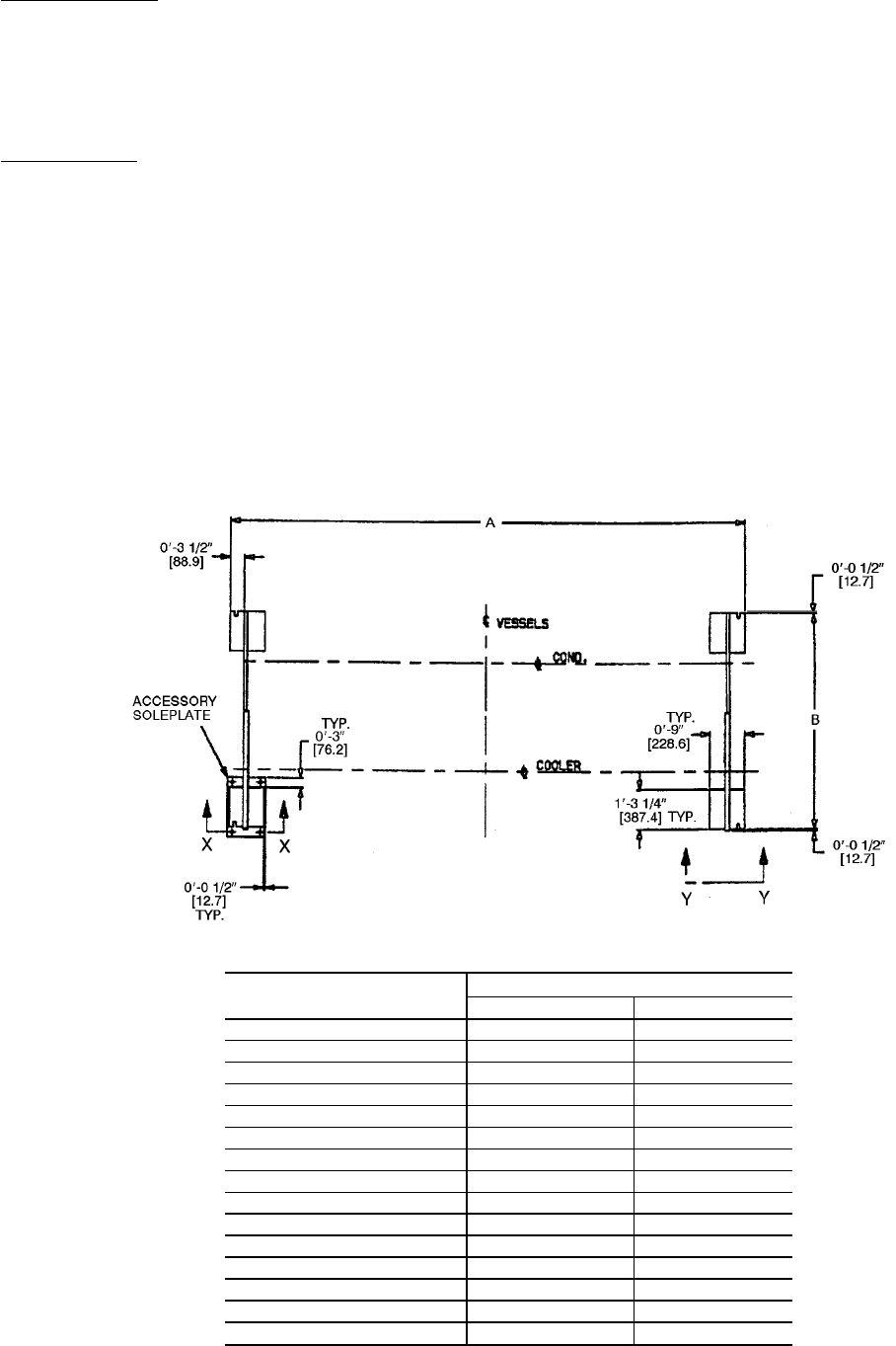
Install Machine Supports
INSTALL STANDARD ISOLATION — Figures 10 and 11
show the position of support plates and shear flex pads, which
together form the standard machine support system.
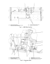
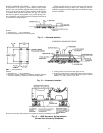
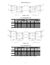
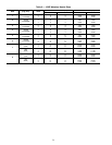
INSTALL ACCESSORY ISOLATION (if required) — Un-
even floors or other considerations may dictate the use of
accessory soleplates (supplied by Carrier for field installa-
tion) and leveling pads. Refer to Fig. 10 and 12.
Level machine by using jacking screws in isolation sole-
plates. Use a level at least 24-in. (600 mm) long.
For adequate and long lasting machine support, proper grout
selection and placement is essential. Carrier recommends that
only pre-mixed, epoxy type, non-shrinking grout be used for
machine installation. Follow manufacturer’s instructions in
applying grout.
1. Check machine location prints for required grout
thickness.
2. Carefully wax jacking screws for easy removal from grout.
3. Grout must extend above the base of the soleplate and
there must be no voids in grout beneath the plates.
4. Allow grout to set and harden, per manufacturer’s in-
structions, before starting machine.
5. Remove jacking screws from leveling pads after grout has
hardened.
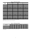
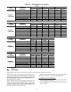
HEAT EXCHANGER
SIZE
DIMENSIONS (ft-in.)
AB
10-12 10- 7
1
⁄
4
4-11
1
⁄
4
15-17 12-10
3
⁄
4
4-11
1
⁄
4
20-22 10- 7
1
⁄
4
5- 5
1
⁄
4
30-32 12-10
3
⁄
4
5- 4
1
⁄
4
35-37 14- 7
1
⁄
4
5- 4
1
⁄
4
40-42 12-10
3
⁄
4
6- 0
45-57 14- 7
1
⁄
4
6- 0
50-52 12-10
3
⁄
4
6- 5
1
⁄
2
55-57 14- 7
1
⁄
4
6- 5
1
⁄
2
60-62 12-10
3
⁄
4
6- 9
1
⁄
2
65-67 14- 7
1
⁄
4
6- 9
1
⁄
2
70-72 15- 1
7
⁄
8
7-10
1
⁄
2
75-77 17- 1
7
⁄
8
7-10
1
⁄
2
80-82 15- 1
7
⁄
8
8- 9
3
⁄
4
85-87 17- 1
7
⁄
8
8- 9
3
⁄
4
Fig. 10 — 19XR Machine Footprint
17