


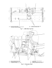
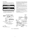
3. Disconnect the compressor discharge elbow at the com-
pressor (Fig. 7, Item 3).
4. Cut the hot gas bypass line at the location shown (Fig. 6,
Item 1).
5. Unbolt the cooler liquid feed line at the location shown
(Fig. 6, Item 10).
6. Cover all openings.
7. Disconnect all wires and cables that cross from the cooler
side of the machine to the condenser side, including:
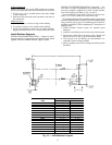
a. temperature sensor cable at the waterbox (Fig. 9,
Item 1)
b. condenser transducer cable at the transducer (Fig. 7,
Item 4)
c. motor power wires at the starter (Fig. 6, Item 4)
d. wires and cable housings at the power panel that cross
from the starter to the power panel (Fig. 7, Item 2).
8. Disconnect the rabbet-fit connectors on the tube sheets
(Fig. 6, Item 5).
9. Rig the vessels apart.
To Separate the Compressor from the Cooler:
1. Unbolt the compressor suction elbow at the cooler flange
(Fig. 6, Item 2).
2. Cut the refrigerant motor cooling line at the location shown
(Fig. 6, Item 7).
3. Disconnect the motor refrigerant return line (Fig. 6,
Item 8).
4. Disconnect the following:
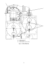
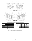
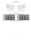
a. compressor oil sump temperature sensor cable
(Fig. 8, Item 4)
b. bearing temperature sensor cable (Fig. 8, Item 2).
c. motor temperature sensor cable (Fig. 8, Item 1)
d. wires and cable housings that cross from the power
panel to the starter and control panel (Fig. 7, Item 2)
e. discharge temperature sensor cable (Fig. 8, Item 6)
f. compressor oil sump pressure cable (Fig. 8, Item 3)
g. compressor oil discharge pressure cable (Fig. 8,
Item 5)
h. guide vane actuator cable (Fig. 7, Item 1).
i. diffuser actuator cable (Frame 5 compressor only —
not shown)
5. Disconnect the flared fitting for the oil reclaim line
(Fig. 6, Item 3).
6. Unbolt the compressor discharge elbow (Fig. 7, Item 3).
7. Cover all openings.
8. Disconnect motor power cables at the starter lugs
(Fig. 6, Item 4).
9. Unbolt the compressor mounting from the cooler
(Fig. 6, Item 9).
10. Rig the compressor.
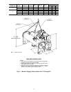
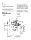
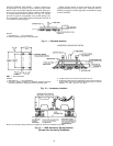
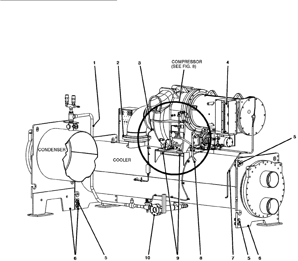
1—Optional Hot Gas Bypass (Cut)
2—Compressor Suction Elbow (Unbolt)
3—Oil Reclaim Line (Unbolt)
4—Starter Connector (Unbolt)
5—Vessel Connectors (Unbolt)
6—Tube Sheet
7—Refrigerant Motor Cooling Line (Cut)
8—Motor Drain (Unbolt)
9—Compressor Mounting (Unbolt)
10 — Cooler Liquid Feed Line (Unbolt)
Fig. 6 — Cooler, Side View
14