


Connect Power Wires to Oil Heater Contactor — Connect
control power wiring between the oil heater contactor ter-
minals and terminals LL1 and LL2 on the field wiring strip
in the compressor motor starter. Refer to Fig. 31 and wiring
label on the machine power panel.
Voltage to terminals LL1 and LL2 comes from a con-
trol transformer in a starter built to Carrier specifica-
tions. Do not connect an outside source of control power
to the compressor motor starter (terminals LL1 and LL2).
An outside power source will produce dangerous volt-
age at the line side of the starter, because supplying volt-
age at the transfomer secondary terminals produces in-
put level voltage at the transformer primary terminals.
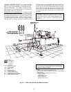
Connect Wiring from Starter to Power Panel — Connect con-
trol wiring from main motor starter to the machine power
panel. All control wiring must use shielded cable.Also, con-
nect the communications cable. Refer to the job wiring dia-
grams for cable type and cable number. Make sure the con-
trol circuit is grounded in accordance with applicable electrical
codes and instructions on machine control wiring label.
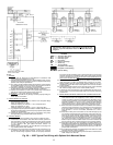
CARRIER COMFORT NETWORK INTERFACE — The
Carrier Comfort Network (CCN) communication bus wiring
is supplied and installed by the electrical contractor. It con-
sists of shielded, 3-conductor cable with drain wire.
The system elements are connected to the communication
bus in a daisy chain arrangement. The positive pin of each
system element communication connector must be wired to
the positive pins of the system element on either side of it.
The negative pins must be wired to the negative pins. The
signal ground pins must be wired to the signal ground pins.
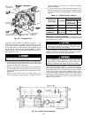
See Fig. 24 for location of the CCN network connector
(COMM1) on the processor module.
NOTE: Conductors and drain wire must be 20 AWG
(American Wire Gage) minimum stranded, tinned copper. In-
dividual conductors must be insulated with PVC, PVC/
nylon, vinyl, Teflon, or polyethylene. An aluminum/polyester
100% foil shield and an outer jacket of PVC, PVC/nylon,
chrome vinyl, or Teflon with a minimum operating tempera-
ture range of −4 F to 140 F (−20 C to 60 C) is required. See
table below for cables that meet the requirements.
MANUFACTURER CABLE NO.
Alpha 2413 or 5463
American A22503
Belden 8772
Columbia 02525
When connecting the CCN communication bus to a sys-
tem element, a color code system for the entire network is
recommended to simplify installation and checkout. The fol-
lowing color code is recommended:
SIGNAL TYPE
CCN BUS CONDUCTOR
INSULATION COLOR
COMM1 PLUG
PIN NO.
+ Red 1
Ground White 2
− Black 3
If a cable with a different color scheme is selected, a simi-
lar color code should be adopted for the entire network.
At each system element, the shields of its communication
bus cables must be tied together. If the communication bus
is entirely within one building, the resulting continuous shield
must be connected to ground at only one single point. See
Fig. 25. If the communication bus cable exits from one build-
ing and enters another, the shields must be connected to ground
at the lightening suppressor in each building where the cable
enters or exits the building (one point only).
To connect the 19XR chiller to the network, proceed as
follows (Fig. 24 and 25):
1. Cut power to the PIC control panel.
2. Remove the COMM1 plug from the processor module.
3. Cut a CCN wire and strip the ends of the RED, WHITE,
and BLACK conductors.
4. Using a wirenut, connect the drain wires together.
5. Insert and secure the RED wire to Terminal 1 of the
COMM1 plug.
6. Insert and secure the WHITE wire to Terminal 2 of the
COMM1 plug.
7. Insert and secure the BLACK wire to Terminal 3 of the
COMM1 plug.
8. Mount a terminal strip in a convenient location.
9. Connect the opposite ends of each conductor to separate
terminals on the terminal strip.
10. Cut another CCN wire and strip the ends of the
conductors.
11. Connect the RED wire to the matching location on the
terminal strip.
12. Connect the WHITE wire to the matching location on
the terminal strip.
13. Connect the BLACK wire to the matching location on
the terminal strip.
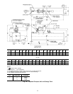
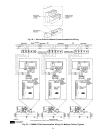
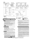
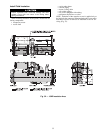
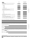
LEGEND
Factory Wiring
Field Wiring
Oil Pump Terminal
Power Panel Component Terminal
Fig. 30 — Oil Pump Wiring
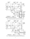
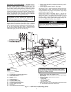
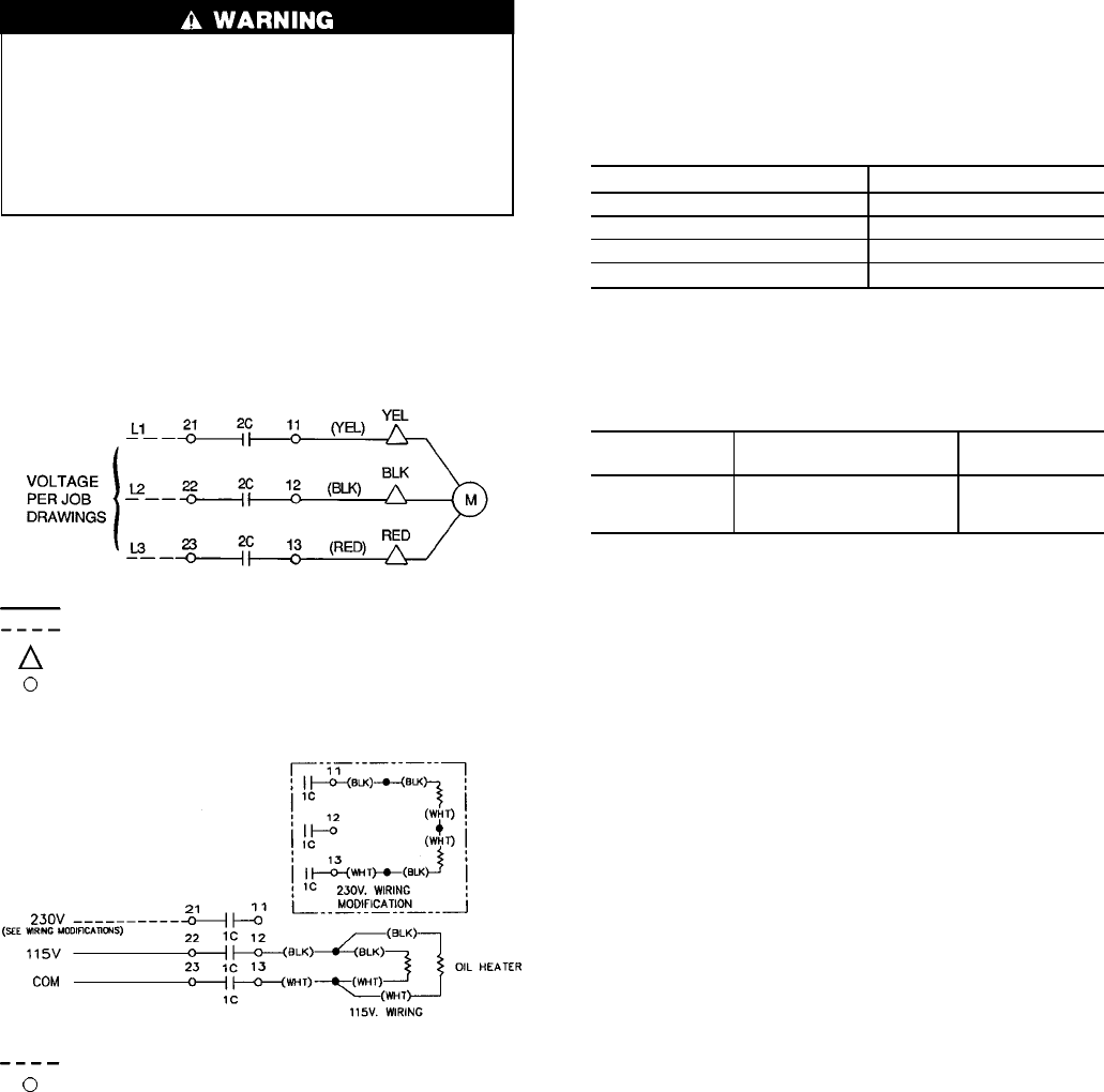
LEGEND
Field Wiring
Power Panel Component Terminal
NOTE: The voltage selector switch in the machine power panel is
factory setfor 115 vcontrol powersource. Whena 230 vcontrol power
source is used, set the voltage selector switch at 230 v.
Fig. 31 — Oil Heater and Control Power Wiring
34