


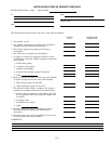

INSTALLATION START-UP REQUEST CHECKLIST
Machine Model Number: 19XR Serial Number:
To:
Attn:
Date
Project Name
Carrier Job Number
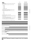
The following information provides the status of the chiller installation.
YES/NO
(N/A)
DATE TO BE
COMPLETED
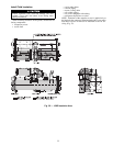
1. The machine is level.
2. The machine components are installed and connected in
accordance with the installation instructions.
3. The isolation package and grouting (if necessary)
are installed.
4. The relief valves are piped to the atmosphere.
5. All piping is installed and supported. Direction of flow
is indicated in accordance with the installation instructions
and job prints.
a. Chilled water piping
b. Condenser water piping
c. Waterbox drain piping
d. Pumpout unit condenser piping (if installed)
e. Other
6. Gages are installed as called for on the job prints required
to establish design flow for the cooler and condenser.
a. Water pressure gages IN and OUT
b. Water temperature gages IN and OUT
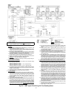
7. The machine’s starter wiring is complete. The wiring is
installed per installation instructions and certified prints.
a. Power wiring to compressor motor. (Motor leads will
not be taped until the Carrier technician megger tests
the motor.)
b. Oil pump wiring
c. Oil heater/control wiring
d. Other
8. The motor starter has not been supplied by Carrier. It
has been installed according to the manufacturer’s
instructions.
9. The motor starter has not been supplied by Carrier and it
has been checked for proper operation.
COMMENTS:
CL-1