


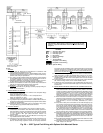


LEGEND
NOTES:
I. GENERAL
1.0 Starters shall be designed and manufactured in accordance with
Carrier Engineering Requirement Z-375.
1.1 All field-supplied conductors, devices, field-installation wiring, and ter-
mination of conductorsand devices must be incompliance with all ap-
plicable codes and job specifications.
1.2 The routing of field-installed conduit and conductors and the location
of field-installed devices must not interfere with equipment access or
the reading, adjusting, or servicing of any component.
1.3 Equipment,installation, and all startingand control devicesmust com-
ply with details in equipment submittal drawings and literature.
1.4 Contacts and switches are shown in the position they would assume
with the circuit deenergized and the chiller shut down.
1.5 WARNING
— Do not use aluminum conductors.
1.6 Installer is responsible for anydamage caused by improper wiring be-
tween starter and machine.
II. POWER WIRING TO STARTER
2.0 Power conductor rating must meet minimum unit nameplate voltage
and compressor motor RLA.
When (3) conductors are used:
Minimum ampacity per conductor = 1.25 x compressor RLA
When (6) conductors are used:
Minimum ampacity per conductor = 0.721 x compressor RLA
2.1 Lugadaptersmay berequiredif installationconditionsdictatethat con-
ductorsbesizedbeyondtheminimum ampacityrequired.Contactstarter
supplier for lug information.
2.2 Compressor motor and controls must be grounded by using equip-
ment grounding lugs provided inside starter enclosure.
III. CONTROL WIRING
3.0 Field supplied control conductors to be at least 18 AWG or larger.
3.1 Chilled water and condenser water flow switch contacts, optional re-
mote start device contacts, and optional spare safety device contacts
must have 24 vdc rating. Max current is 60 mA; nominal current is
10 mA. Switches with gold plated bifurcated contacts are
recommended.
3.2 Remove jumper wire between 12A and 12B before connecting auxil-
iary safeties between these terminals.
3.3 Pilotrelays can controlcooler and condenserpump and towerfan mo-
tor contactor coil loads rated 10 amps at 115 vac up to 3 amps at
600 vac. Control wiring required for Carrier to start pumps and tower-
fan motors must be provided to assure machine protection. If primary
pump andtower fanmotor are controlledby othermeans, alsoprovide
aparallel meansfor controlby Carrier. Donot usestarter controltrans-
former as the power source for pilot relay loads.
3.4 Donot route control wiring carrying 30v or less within aconduit which
has wires carrying 50 v or higher or alongside wires carrying 50 v or
higher.
3.5 Voltage selector switch in machine power panel is factory set for
115 vcontrol powersource. When230 vcontrol power sourceis used,
set switch to 230 v position.
3.6 Controlwiringcablesbetweenstarterand powerpanelmustbeshielded
with minimum rating of 600 v, 80 C. Ground shield at starter.
3.7 Ifoptional oil pump circuitbreaker is not suppliedwithin the starteren-
closure as shown, it must be located within sight of the machine with
wiring routed to suit.
3.8 For 19XR chillers with free-standing starts, voltage to terminals LL1
and LL2 comes from a control transformer in a starter built to Carrier
specifications. Do not connect an outside source of control power to
thecompressormotorstarter terminals(LL1andLL2).Anoutsidepower
source will produce dangerous voltage at the line side of the starter,
becausesupplying voltageatthetransformer secondaryterminalspro-
duces input level voltage at the transformer primary terminals.
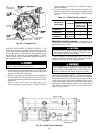
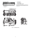
IV. POWER WIRING BETWEEN STARTER AND COMPRESSOR MOTOR
4.0 Lowvoltage (600v or less)compressor motorshave (6)
3
⁄
4
in. terminal
studs (lead connectors not supplied by Carrier). Either 3 or 6 leads
mustberun betweencompressormotorand starter, dependingontype
of motor starter employed. If only 3 leads are required, jumper motor
terminals as follows: 1 to 6, 2 to 4, 3 to 5. Center to center distance
betweenterminalsis 2
15
⁄
16
inches.Compressormotor startermusthave
nameplate stamped as conforming with Carrier requirement Z-375.
4.1 When more than one conduit is used to runconductors from starter to
compressor motor terminal box, oneconductor from each phase must
be in each conduit to prevent excessive heating. (e.g., conductors to
motor terminals 1,2&3inoneconduit, and those to 4,5&6in
another.)
4.2 Compressor motor power connections can be made through top, top
rear,or sidesofcompressor motorterminalboxusing holescutbycon-
tractor to suit conduit. Flexible conduit should be used for the last few
feet to the terminal box for unit vibrationisolation. Use of stress cones
or 12 conductors larger than 500 MCM may require an oversize (spe-
cial) motor terminal box (not supplied by Carrier). Lead connections
between 3-phase motors and their starters must not be insulated until
Carrier personnel have checked compressor and oil pump rotations.
4.3 Compressor motor frame to be grounded in accordance with the Na-
tionalElectricalCode(NFPA-70)andapplicablecodes.Meansforground-
ing compressor motor is a pressure connector for No. 4 to 500 MCM
wire,supplied andlocatedin thebacklower leftsidecorner ofthecom-
pressor motor terminal box.
4.4 Donotallowmotorterminalsto supportweightofwirecables. Usecable
supports and strain reliefs as required.
4.5 Usebackupwrench whentightening leadconnectorsto motorterminal
studs. Torque to 45 lb-ft max.
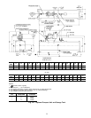
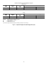
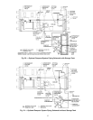
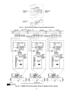
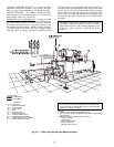
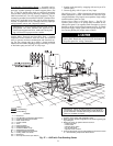
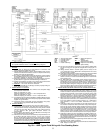
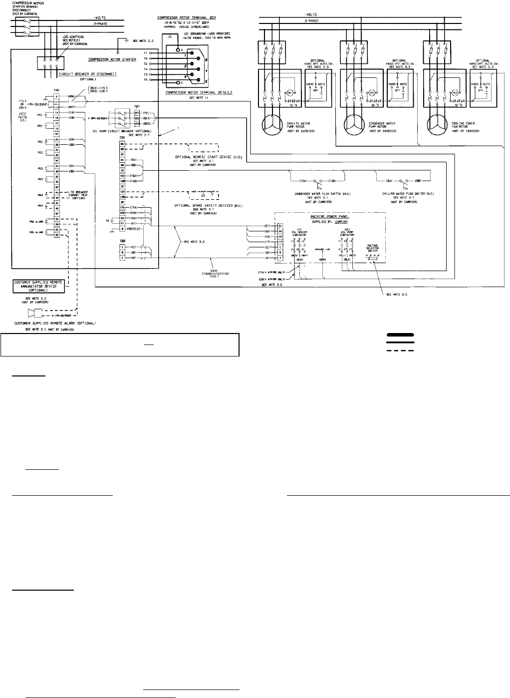
Fig. 29 — 19XR Typical Field Wiring with Free-Standing Starter
IMPORTANT: Wiring shown is typical and not intended to show detail
for a specific installation. Refer to certified field wiring diagrams.
AWG — American Wire Gage
N.C. — Normally Closed
N.O. — Normally Open
PR — Pilot Relay
RLA — Rated Load Amps
SMM — Starter Management
Module
TB — Terminal Block
Required Power Wiring
Required Control Wiring
Options Wiring
33