


CONTENTS
Page
SAFETY CONSIDERATIONS ..................1
INTRODUCTION .............................2
General .....................................2
Job Data ....................................2
INSTALLATION .............................2-35
Receiving the Machine .......................2
• INSPECT SHIPMENT
• IDENTIFY MACHINE
• PROVIDE MACHINE PROTECTION
Rigging the Machine .........................2
• RIG MACHINE ASSEMBLY
• RIG MACHINE COMPONENTS
Install Machine Supports ....................17
• INSTALL STANDARD ISOLATION
• INSTALL ACCESSORY ISOLATION
• INSTALL SPRING ISOLATION
Connect Piping .............................19
• INSTALL WATER PIPING TO HEAT
EXCHANGERS
• INSTALL VENT PIPING TO
RELIEF VALVES
Make Electrical Connections ................28
• CONNECT CONTROL INPUTS
• CONNECT CONTROL OUTPUTS
• CONNECT STARTER
• CARRIER COMFORT NETWORK INTERFACE
Install Field Insulation ......................35
INSTALLATION START-UP REQUEST
CHECKLIST ........................CL-1, CL-2
INTRODUCTION
General —
The 19XR machine is factory assembled, wired,
and leak tested. Installation (not by Carrier) consists
primarily of establishing water and electrical services to
the machine. The rigging, installation, field wiring, field pip-
ing, and insulation of waterbox covers are the responsibility
of the contractor and/or customer. Carrier has no installation
responsibilities for the equipment.
Job Data
Necessary information consists of:
• job contract or specifications
• machine location prints
• rigging information
• piping prints and details
• field wiring drawings
• starter manufacturer’s installation details
• Carrier certified print
INSTALLATION
Receiving the Machine
INSPECT SHIPMENT
Do not open any valves or loosen any connections. The
standard 19XR machine is shipped with a full refrig-
erant charge. Some machines may be shipped with a ni-
trogen holding charge as an option.
1. Inspect for shipping damage while machine is still on ship-
ping conveyance. If machine appears to be damaged or
has been torn loose from its anchorage, have it examined
by transportation inspectors before removal. Forward claim
papers directly to transportation company. Manufacturer
is not responsible for any damage incurred in transit.
2. Check all items against shipping list. Immediately notify
the nearest Carrier representative if any item is missing.
3. To prevent loss or damage, leave all parts in original pack-
ages until beginning installation. All openings are closed
with covers or plugs to prevent dirt and debris from en-
tering machine components during shipping. A full op-
erating oil charge is placed in the oil sump before
shipment.
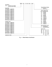
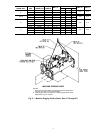
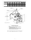
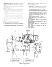
IDENTIFY MACHINE — The machine model number,
serial number, and heat exchanger sizes are stamped on
machine identification nameplate (Fig. 1 and 2). Check this
information against shipping papers and job data.
PROVIDE MACHINE PROTECTION — Protect machine
and starter from construction dirt and moisture. Keep pro-
tective shipping covers in place until machine is ready for
installation.
If machine is exposed to freezing temperatures after water
circuits have been installed, open waterbox drains and re-
move all water from cooler and condenser. Leave drains open
until system is filled.
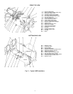
Rigging the Machine — The 19XR machine can be
rigged as an entire assembly. It also has flanged connections
that allow the compressor, cooler, and condenser sections to
be separated and rigged individually.
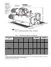
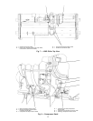
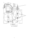
RIG MACHINEASSEMBLY — See rigging instructions on
label attached to machine. Also refer to rigging guide
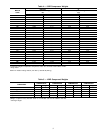
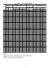
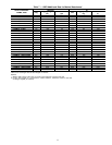
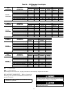
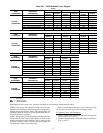
(Fig. 3 and 4), physical data in Fig. 5, and Tables 1-8B. Lift
machine only from the points indicated in rigging guide. Each
lifting cable or chain must be capable of supporting the en-
tire weight of the machine.
Lifting machine from points other than those specified
may result in serious damage to the unit and personal
injury. Rigging equipment and procedures must be ad-
equate for machine weight. See Fig. 3 and 4 for ma-
chine weights.
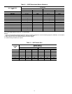
NOTE: These weights are broken down into compo-
nent sections for use when installing the unit in
sections. For the complete machine weight, add all com-
ponent sections and refrigerant charge together. See
Tables 4-8B for machine component weights.
IMPORTANT: Ensure that rigging cable is over the
guide bolt or cable hook on the motor end cover be-
fore lifting if cooler size is 10 through 67.
2