


Connect Piping
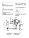
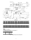
INSTALL WATER PIPING TO HEAT EXCHANGERS —
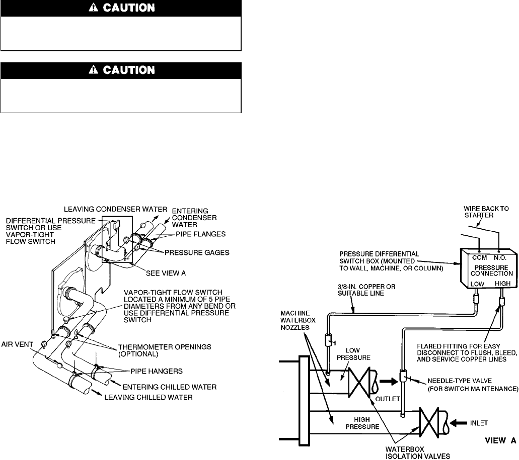
Install piping using job data, piping drawings, and proce-
dures outlined below. A typical piping installation is shown
in Fig. 14.
Factory-supplied insulation is not flammable but can be
damaged by welding sparks and open flame. Protect in-
sulation with a wet canvas cover.
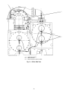
Remove chilled and condenser water sensors before
welding connecting piping to water nozzles. Refer to
Fig. 9. Replace sensors after welding is complete.
1. Offset pipe flanges to permit removal of waterbox cover
for maintenance and to provide clearance for pipe clean-
ing. No flanges are necessary with marine waterbox
option; however, water piping should not cross in front
of the waterbox or access will be blocked.
2. Provide openings in water piping for required pressure
gages and thermometers. For thorough mixing and tem-
perature stabilization, wells in the leaving water pipe should
extend inside pipe at least 2 in. (50 mm).
3. Install air vents at all high points in piping to remove air
and prevent water hammer.
4. Install pipe hangers where needed. Make sure no weight
or stress is placed on waterbox nozzles or flanges.
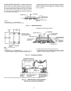
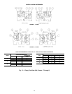
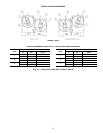
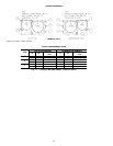
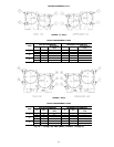
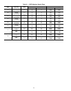
5. Water flow direction must be as specified in Fig. 15-18.
NOTE: Entering water is always the lower of the 2 nozzles.
Leaving water is always the upper nozzle for cooler or
condenser.
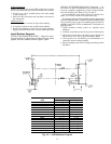
6. Water flow switches must be of vapor-tight construction
and must be installed on top of pipe in a horizontal run
and at least 5 pipe diameters from any bend.
7. Install waterbox vent and drain piping in accordance with
individual job data. All connections are
3
⁄
4
-in. FPT.
8. Install waterbox drain plugs in the unused waterbox drains
and vent openings.
9. Install optional pumpout system or pumpout system and
storage tank as shown in Fig. 19-22.
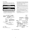
LEGEND
COM — Common
N.O. — Normally Open
*Do not tap connections after shutoff valve.
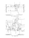
Fig. 14 — Typical Nozzle Piping
*
*
19