


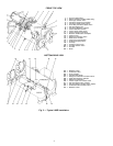
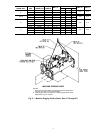
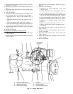
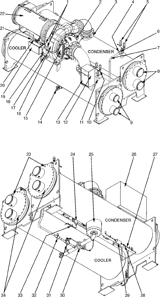
1—Oil Level Sight Glass
2—Diffuser Actuator (Hidden/19XR5 Only)
3—Discharge Isolation Valve
4—Condenser Pumpout Connection
5—Condenser Safety Relief Valves
6—Three-Way Condenser Relief Valve
7—Hot Gas Bypass Line
8—Condenser Waterbox Nozzles
9—Cooler Waterbox Nozzles
10 — Cooler Safety Relief Valves
11 — Cooler Pumpout Connection
12 — Machine Identification Nameplate
13 — Control Panel
14 — Refrigerant Charging Valve
15 — Guide Vane Actuator
16 — Compressor/Transmission
17 — Oil Drain/Charging Valve
18 — Oil Pump
19 — Auxillary Power Panel
20 — Oil Filter Isolation Valve
21 — Oil Filter
22 — Motor
FRONT TOP VIEW
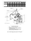
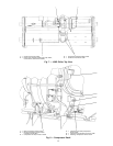
BOTTOM REAR VIEW
23 — Waterbox Vents
24 — Oil Reclaim Filter
25 — Float Chamber
26 — Unit Mounted Starter
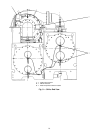
27 — Refrigerant Filter/Drier Isolation Valves
28 — Sight Glass/Moisture Indicator
29 — Refrigerant Filter/Drier
30 — Cooler Liquid Line Isolation Valve
31 — Hot Gas Bypass Valve (Option)
32 — Hot Gas Bypass Isolation Valve (Option)
33 — Oil Reclaim Filter Isolation Valve
34 — Waterbox Vents
Fig.2—Typical 19XR Installation
4