


CAUTION: Due to the high pressure of nitrogen, it
should never be used without a pressure regulator on the
tank.
Leaks in a system pressurized with refrigerant can be spotted with
a leak detector that detects extremely small refrigerant leaks. This
discussion assumes that system is pressurized with either all
refrigerant or a mixture of nitrogen and refrigerant.
If system has been operating for some time, make first check for
a leak visually. Since refrigerant carries a small quantity of oil,
traces of oil at any joint or connection are an indication that
refrigerant is leaking at that point.
A simple and inexpensive method of testing for leaks is to use soap
bubbles. Any solution of water and soap may be used. Soap
solution is applied to all joints and connections in system. A small
pinhole leak is located by tracing bubbles in soap solution around
leak.
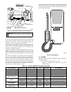
Use electronic leak detector to check for leaks. This unquestion-
ably is the most efficient and easiest method for checking leaks.
There are various types of electronic leak detectors. Generally
speaking, they are all portable, and most are lightweight, consist-
ing of a box with several switches and a probe or sniffer. Detector
is turned on and probe is passed around all fittings and connections
in system. Leak is detected by either a movement of a pointer on
detector dial, by a buzzing sound, or a light.
In all instances, when a leak is found, system charge must be bled
down and leak repaired before final charging and operation. After
leak testing or leak is repaired, evacuate system, and recharge with
correct refrigerant charge.
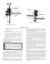
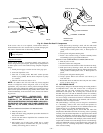
III. BRAZING
When brazing is required in the refrigeration system, certain basics
should be followed:
1. Clean joints make the best joints. To clean:
a. Remove all oxidation from surfaces to a shiny finish
before brazing.
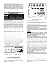
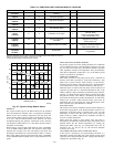
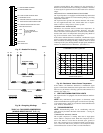
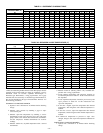
TABLE 19—24V PIN CONNECTION TROUBLESHOOTING
MODE OF OPERATION
18-PIN CONNECTOR
TERMINAL
DESIGNATION
LOCATION ON
CONTROL BOARD
VOLTAGE
PATH
VOLTAGE
REQUIRED
POSSIBLE SOURCE
OF PROBLEM
All R-C 2-1 Input 24 Check transformer (secondary)
Low-speed Cooling Y1,0-C 8,6-1 Input 24 Check thermostat
High-speed Cooling Y1, Y2, 0-C 8,7,6-1 Input 24 Check thermostat
Low-speed Heating Y1-C 8-1 Input 24 Check thermostat
High-speed Heating
Y1-C 8-1 Input 24 Check thermostat
Y2-C 7-1 Output 24
Outdoor temperature below
speed; change temperature
Defrost
Y1-C 8-1 Input 24 Check thermostat
Y2, W2, 0-C 7,5,6-1 Output 24
Outdoor temperature below 50°F;
Coil temperature less than 30°F
Second Stage of
Auxiliary Heat
Y1, W2-C 7,5-1 Input 24 Check thermostat
W3, Y2-C 9,8-1 Output 24 Check balance-point setting
Cooling Second-
stage Latching
Y1, Y2, 0-C 8,7,6-1 Input 24
Ambient thermistor failure;
Check second-stage POT
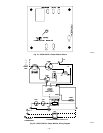
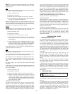
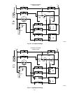
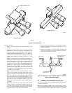
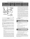
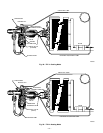
Fig. 42—Heat Pump Refrigerant-Flow Diagrams
A88400
COOLING CYCLE
INDOOR COIL
OUTDOOR FAN
REVERSING VALVE
(ENERGIZED)
ACCUMULATOR
OUTDOOR
COIL
LIQUID LINE
PRESSURE SWITCH
(BYPASSING)
COMP
STRAINER
STRAINER
SUCTION
SERVICE
PORT
SUCTION SERVICE
PORT AT SERVICE
VALVE (CLG CYCLE)
(METERING)
INDOOR
FAN
LIQUID LINE SERVICE PORT
AT SERVICE VALVE (CLG CYCLE)
HEAT PUMP
ACCESSORY
FILTER DRIER
(DUAL FLOW)
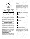
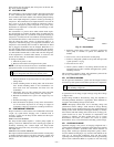
Fig. 43—Leak Detector
A88401
—37—