In this type of failure, compressor motor runs and turns compres-
sor, and compressor is pumping. Usually, an internal problem such
as blown head gasket or broken internal-discharge line causes
compressor to pump hot discharge gas back into its own shell
rather than through system.
Using pressure gages on service valves shows high suction and
low discharge pressure readings. Motor currents are lower than
normal. Because hot gas is being discharged into shell, the shell
becomes hot. The hot gas causes compressor motor to cycle off on
its internal protection.
RUNS AND PUMPS, LOW CAPACITY
This failure type is difficult to pinpoint because extent of damage
varies. Compressor is a pump with internal valves that enable
compressor to pump properly. The cylinder has a set of suction and
discharge valves. Any of these parts may become damaged or
broken, causing loss in pumping capacity. Severity of damage
determines amount of capacity loss. Use pressure gages to find any
abnormal system pressures if system charge and other conditions
are normal.
An owner may complain that a unit is not handling the building’s
heating or cooling load. The compressor current draw may be
abnormally low or high. Although this type of failure does occur,
all other possible causes of capacity loss must be eliminated before
condemning compressor.
NOISY COMPRESSOR
Noise may be caused by a variety of internal problems such as
loosened hardware, broken mounting springs, etc. System prob-
lems such as overcharged compressor (especially at start-up) or too
much oil in compressor may also cause excessive noise. Excess oil
in compressor is normally encountered only after a replacement
compressor has been added without purging oil from previous
compressor. As new compressor pumps, excess oil in system
returns and adds to volume already present, causing noise.
COMPRESSOR LEAKS
CAUTION: Use safety glasses and gloves when han-
dling refrigerants.
Sometimes a leak is detected at weld seam around girth of
compressor or a fitting that joins compressor shell. Many of these
leaks can be repaired and the compressor saved if correct proce-
dure is followed.
1. Turn off all power to unit.
2. Remove and recover all refrigerant from system so that
gage pressures are 0 psi.
3. Clean area around leak to bare metal.
4. Apply flux and repair joint with silver solder. Do not use
low-temperature solder such as 50-50.
5. Clean off excess flux, check for leaks, and apply paint over
repaired area to prevent corrosion.
Do not use this method to repair a compressor leak due to severe
corrosion. Never attempt to repair a compressor leaking at electric
terminals. This type of failure requires compressor replacement.
II. ELECTRICAL FAILURES
The compressor mechanical pump is driven by an electric motor
within its hermetic shell. In electrical failures, compressor does not
run although external electrical and mechanical systems appear
normal. Compressor must be checked electrically for abnormali-
ties.
Before troubleshooting compressor motor, review this description
of compressor motor-terminal identification.
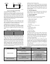
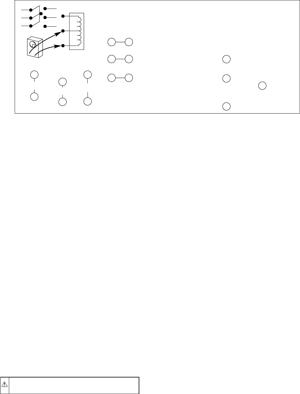
SINGLE-PHASE MOTORS
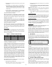
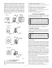
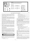
To identify terminals C, S, and R:
1. Turn off all unit power.
2. Short the run and start capacitors to prevent shock.
3. Remove all wires from motor terminals.
4. Read resistance between all pairs of terminals using an
ohmmeter on 0-10 ohm scale.
5. Determine 2 terminals that provide greatest resistance
reading.
Through elimination, remaining terminal must be common (C).
Greatest resistance between common (C) and another terminal
indicates start winding because it has more turns. This terminal is
start (S). Remaining terminal will be run winding (R). (See Fig.
28.)
NOTE: If compressor is hot, allow time to cool and internal line
break to reset. There is an internal line-break protector which must
be closed.
THREE-PHASE MOTORS
Resistance readings between all 3 sets of windings should be the
same.
All compressors are equipped with internal motor protection. If
motor becomes hot for any reason, protector opens. Compressor
should always be allowed to cool and protector to close before
troubleshooting. Always turn off all power to unit and disconnect
leads at compressor terminals before taking readings.
Fig. 28—Identifying Internal Connections
A88344
POWER OFF!
OHMMETER
0-10Ω SCALE
5.2Ω
0.6Ω
5.8Ω
DEDUCTION:
(EXAMPLE)
TO DETERMINE INTERNAL CONNECTIONS OF SINGLE-
PHASE MOTORS (C,S,R) EXCEPT SHADED-POLE
?
?
?
1
2
2
3
1
3
12
32
1 3 (GREATEST RESISTANCE)
5.8Ω (OHM)
(SMALLEST RESISTANCE)
0.6Ω
(REMAINING RESISTANCE)
5.2Ω
2
2
3
1
IS COMMON (C)
BY ELIMINATION
IS COMMON,
THEREFORE, IS
START WINDING (S)
RUN WINDING (R)
START WINDING (S)
IS RUN WINDING (R)
—26—


