


heat-pump output drops. Setting at which thermostat closes is
variable, depending on design of system. It is set at time of
installation and should not be changed without cause. Up to 2
outdoor thermostats may be installed. Some systems may not have
any thermostat. An outdoor thermostat can also be used to lock out
compressor operation at low ambients in condensing unit not
equipped with low-ambient control.
Although these devices are installed in control circuit (24v), turn
off all power to unit before attempting to troubleshoot thermostat.
Use a standard ohmmeter to check for continuity through thermo-
stat. If you suspect thermostat is out of calibration, use calibrated
electronic thermometer to determine correct outdoor temperature.
Turn thermostat dial knob until switch closes. Observe this using
ohmmeter across switch. Read temperature setting when switch
closes. It should be close to reading observed using electronic
thermometer. Any setting within ± 5°F is acceptable.
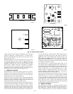
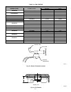
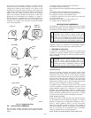
XIII. COMPRESSOR PLUG
The compressor electrical plug provides a quick-tight connection
to the compressor terminals. The plug completely covers the
compressor terminals, and the mating female terminals are com-
pletely encapsulated in the plug. Therefore, the terminals are
isolated from any moisture so corrosion and resultant pitted or
discolored terminals are reduced. The plug is oriented to the relief
slot in the terminal box so the cover cannot be secured if wires are
not positioned in slot, assuring correct electrical connection at the
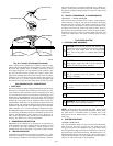
compressor. The plug can be removed by simultaneously pulling
while ″rocking″ the plug. However, these plugs are specialized and
vary in terminal orientation in the plug. Therefore, plugs can be
used on only the specific compressor or group as shown in Fig. 27.
For the Carlyle and Bristol compressors in Fig. 27, the triangle
formed by the fusite terminals points down, and the plug is
likewise oriented. The fusite terminals and plug-terminal orienta-
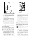
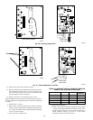
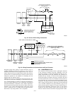
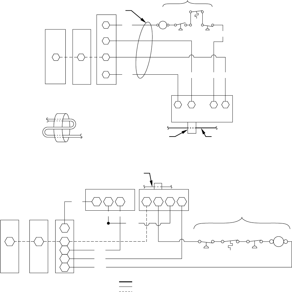
Fig. 25—Service Alarm Wiring Connections
A88340
Y
L
C
LL
C
BLK
THERMOSTAT
SUBBASE
INDOOR
UNIT
TERMINAL
BOARD
OUTDOOR
UNIT
TERMINAL
BOARD
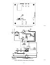
PASS SUPPLY WIRE THROUGH
METALLIC LOOP TWICE ON
UNITS WITH NAMEPLATE
RLA OF 14 AMPS OR LESS.
C
21 3 X
YEL
SERVICE ALARM
ORN REDYEL
BRN
YEL
LPS
DTS
HPS
BLUBLU
HIGH AND/OR LOW PRESSURE
AND/OR DISCHARGE TEMPERATURE
SWITCH (IF USED)
24-VOLT WIRING
*METALLIC
LOOP
ONE FIELD
LINE VOLTAGE
SUPPLY WIRE
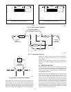
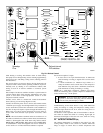
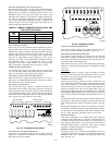
Fig. 26—Wiring Connections for Service Alarm and Cycle Protector
A88339
A88339
T1
FIELD LINE VOLTAGE SUPPLY WIRE
T2 T3 X 3 2 1
Y
L
C
C
C
LL
C
YEL
BLK
BLK
BRN
THERMOSTAT
SUBBASE
INDOOR
UNIT
TERMINAL
BOARD
OUTDOOR
UNIT
TERMINAL
BOARD
ORN
BLKVIO
YEL
LPS
DTS
HPS
YEL BLU BLU
BRN
HIGH AND/OR LOW PRESSURE
AND/OR DISCHARGE TEMPERATURE
SWITCH (IF USED)
COMMON POTENTIAL
FACTORY WIRING (FIELD CONNECTED)
FIELD-SUPPLIED WIRING
CONTACTOR
CYCLE PROTECTOR SERVICE ALARM
C
—24—