


IX. WIND BAFFLE
A field-fabricated sheet-metal cover used to stop prevailing winds
or where outdoor ambient temperature is less than 55°F during unit
operation of cooling mode.
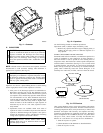
X. COASTAL FILTER
A mesh screen inserted under top cover and inside base pan to
protect condenser coil from salt damage without restricting air-
flow.
XI. SUPPORT FEET
Four adhesive plastic feet which raise unit 4 in. above mounting
pad. This allows sand, dirt, and other debris to be flushed from unit
base; minimizes corrosion.
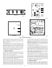
XII. LIQUID-LINE SOLENOID VALVE
An electrically operated shutoff valve to be installed at outdoor or
indoor unit (depending on tubing configuration) which stops and
starts refrigerant liquid flow in response to compressor operation.
Maintains a column of refrigerant liquid ready for action at next
compressor-operation cycle and prevents liquid migration during
the off cycle.
XIII. THERMOSTATIC-EXPANSION VALVE
A modulating flow-control device which meters refrigerant flow
rate into the evaporator in response to the superheat of the
refrigerant gas leaving the evaporator. Only use factory-specified
TXV’s.
XIV. ISOLATION RELAY
A DPDT relay which switches the low-ambient controller out of
the outdoor fan-motor circuit when the heat pump switches to
heating mode.
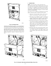
LOW-AMBIENT GUIDELINE
The minimum operating temperature for these units in cooling
mode is 55°F outdoor ambient without additional accessories. This
equipment may be operated in cooling mode at ambient tempera-
tures below 55°F when the accessories listed in Table 1 are
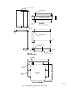
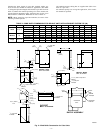
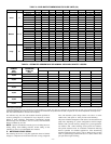
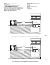
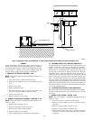
installed. Wind baffles are required when operating in cooling
mode at ambients below 55°F. Refer to Fig. 1 or 2 and Table 2 or
3 for wind baffle construction details.
LONG-LINE GUIDELINE
This Long-Line Application Guideline applies to all Bryant
residential air conditioner and heat pump split systems that have a
nominal capacity of 18,000 to 60,000 Btuh. This guideline
provides required system changes and accessories necessary for
any residential product having piping requirements greater than 50
ft or installations where indoor unit is located above outdoor unit.
This guideline is intended to cover applications outside the
standard Installation Instructions. This guideline is for standard,
single-speed products. For applications involving 2-speed prod-
ucts, refer to Section VI first.
NOTE: The presale literature for outdoor unit must be referred to
in conjunction with this guideline.
I. APPROVED SYSTEMS
Any residential indoor/outdoor unit combination listed in the
outdoor unit presale literature is an approved system, EXCEPT the
following:
• Indoor coils with capillary-metering devices
• All equipment less than nominal 18,000 Btuh
• All 1/4-in. and 5/16–in. liquid-line applications
• Any indoor furnace coil/fan coil not listed in outdoor unit
presale literature
• Any application which has interconnecting tubing with an
equivalent length greater than 175 ft
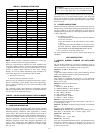
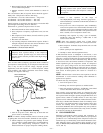
II. INTERCONNECTING TUBING SIZING
Table 4 lists recommended interconnecting vapor-line diameters
for equivalent total-line lengths. All residential split systems
installed in long-line applications must use only 3/8-in. liquid
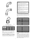
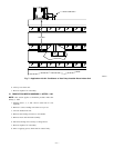
lines. Equivalent line length equals the linear length (measured) of
interconnecting vapor tubing plus losses due to elbows. (See Table
5 and Fig. 3.) Liquid lines larger than 3/8-in. OD greatly increase
charge quantity of the system. Excessive charge increases risk of
migration and compressor damage. Table 4 provides the estimated
percentage of nominal cooling-capacity losses based on the stan-
dard, required vapor line size versus what is selected for the
long-line application. Since the vapor line is the discharge line in
heating mode, losses are minimal.
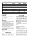
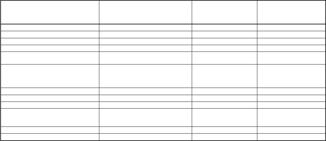
TABLE 1—REQUIRED FIELD-INSTALLED ACCESSORIES FOR AIR CONDITIONERS AND HEAT PUMPS
ACCESSORY
REQUIRED FOR
LOW-AMBIENT
APPLICATIONS
(BELOW 55°F)
REQUIRED FOR
LONG-LINE
APPLICATIONS*
(OVER 50 FT)
REQUIRED FOR
SEA COAST
APPLICATIONS
(WITHIN 2 MILES)
Crankcase Heater Yes Yes No
Evaporator Freeze Thermostat Yes No No
Winter Start Control Yes† No No
Accumulator No No No
Compressor Start Assist
Capacitor and Relay
Yes Yes No
Low Ambient Controller,
MotorMaster™ Control,
or
Low-Ambient Pressure Switch
Yes No No
Wind Baffle See Low-Ambient Instructions No No
Coastal Filter No No Yes
Support Feet Recommended No Recommended
Liquid-Line Solenoid Valve
or
Hard-Shutoff TXV
No
See Long-Line
Application
Guideline
No
Ball-Bearing Fan Motor Yes‡ No No
Isolation Relay Yes** No No
*For tubing line sets between 50 and 175 ft, refer to Residential Split-System Long-Line Application Guideline.
†Only when low-pressure switch is used.
‡Required for Low-Ambient Controller (full modulation feature) and MotorMaster™ control only.
** Required on Heat Pumps only.
—3—