


connection will be exposed to moisture, it is very important to
cover the entire connection completely to prevent an electrochemi-
cal action that will cause the connection to fail very quickly. Do
not reduce the effective size of wire, such as cutting off strands so
that the wire will fit a connector. Proper size connectors should be
used. Check all factory and field electrical connections for
tightness. This should also be done after the unit has reached
operating temperatures, especially if aluminum conductors are
used.
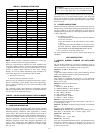
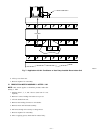
II. CONTACTORS
NOTE: The section applies to single-speed models only.
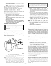
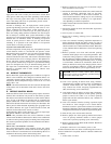
The contactor provides a means of applying power to unit using
low voltage (24v) from transformer in order to power the contactor
coil. (See Fig. 11.) Depending on unit model, you may encounter
single-, double-, or triple-pole contactors to break power. One side
of the line may be electrically energized, so exercise extreme
caution when troubleshooting.
The contactor coil for residential air-conditioning units and heat
pumps is powered by 24vac. If contactor does not operate:
1. With power off, check whether contacts are free to move.
Check for severe burning or arcing on contact points.
2. With power off, use ohmmeter to check for continuity of
coil. Disconnect leads before checking. A low-resistance
reading is normal. Do not look for a specific value, as
different part numbers have different resistance values.
3. Reconnect leads and apply low-voltage power to contactor
coil. This may be done by leaving high-voltage power to
outdoor unit off, and turning thermostat to heat or cool.
Check voltage at coil with voltmeter. Reading should be
between 20v and 30v. Contactor should pull in if voltage is
correct and coil is good. If contactor does not pull in,
change contactor.
4. With high-voltage power off and contacts pulled in, check
for continuity across contacts with ohmmeter. A very low or
zero resistance should be read. Higher readings could
indicate burned or pitted contacts which may cause future
failures.
SEFL JOSDJ
SEFL JOSDJ
SEFL JOSDJ
SEFL JOSDJ
SEFL JOSDJ
SEFL JOSDJ
SEFL JOSDJ
SEFL JOSDJ PAASFLDLKREW
SEFL JOSDJ
SEFL JOSDJ ATC
SEFL JOSDJ
SEFL JOSDJ UTUHD
SEFL JOSDJ
SEFL JOSDJC MD
SEFL JOSDJ
SEFL JOSDJHR ITYALK
SEFL JOSDJ
SEFL JOSDJ
A88412
SEFL JOSDJ
SEFL JOSDJ
SEFL JOSDJ
SEFL JOSDJ
SEFL JOSDJ
SEFL JOSDJ
SEFL JOSDJ
SEFL JOSDJ PAASFLDLKREW
SEFL JOSDJ
SEFL JOSDJ ATC
SEFL JOSDJ
SEFL JOSDJ UTUHD
SEFL JOSDJ
SEFL JOSDJC MD
SEFL JOSDJ
SEFL JOSDJHR ITYALK
SEFL JOSDJ
SEFL JOSDJ
A88413
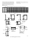
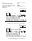
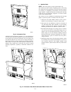
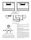
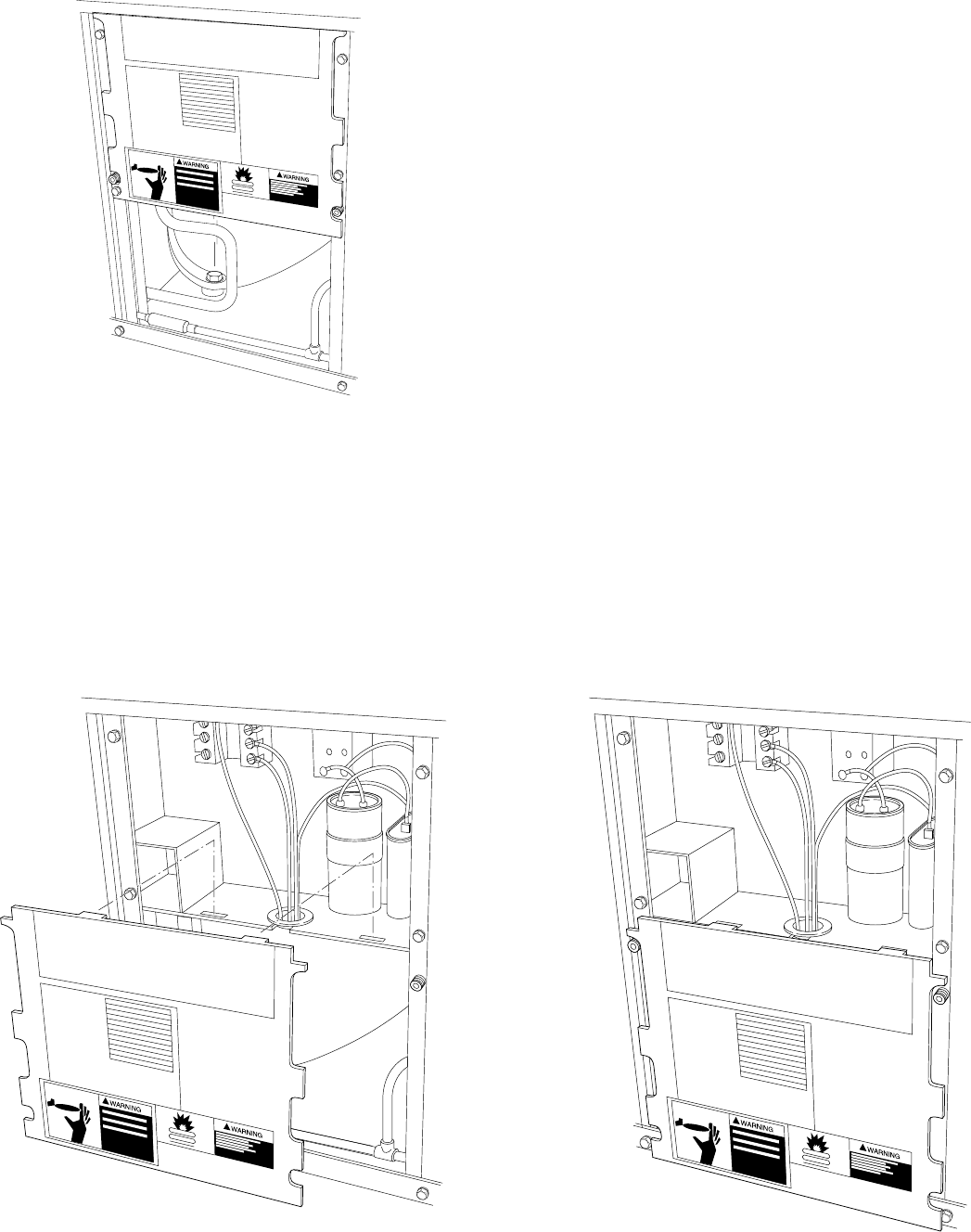
Fig. 10—Information Plate Removed/Installed Below Control Box
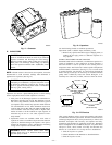
Fig. 9—Information Plate
A88411
SEFL JOSDJ
SEFL JOSDJ
SEFL JOSDJ
SEFL JOSDJ
SEFL JOSDJ
SEFL JOSDJ
SEFL JOSDJ
SEFL JOSDJ PAASFLDLKREW
SEFL JOSDJ
SEFL JOSDJ ATC
SEFL JOSDJ
SEFL JOSDJ UTUHD
SEFL JOSDJ
SEFL JOSDJC MD
SEFL JOSDJ
SEFL JOSDJHR ITYALK
SEFL JOSDJ
SEFL JOSDJ
—13—