


DEFROST
The 2-speed control logic for the defrost function is the standard
time and temperature initiated, time or temperature terminated.
Defrost occurs only at outdoor temperatures less than 50°F. The
control initiates defrost when the outdoor coil thermistor is 30°F(±
2) or less, and the selected defrost time (interval) has been
accumulated during unit operation. Termination occurs when the
coil thermistor reaches 80°F (± 5) or the defrost period reaches a
maximum of 10 minutes.
Defrost always occurs in high speed unless the stage–2 latch POT
is set at ZONE. During defrost the unit operates in high speed,
energizes the reversing valve (O) and auxiliary heat (W2), and
de-energizes the outdoor fan. Upon termination, there is a 20-sec
delay in the outdoor fan being energized. If the stage–2 latch POT
is set to ZONE and the heat pump is in low speed, it defrosts in low
speed.
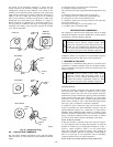
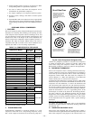
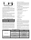
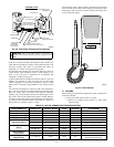
FIELD-INITIATED FORCED DEFROST
By placing a jumper across the speedup terminals for a minimum
of 5 sec and then removing it, the unit initiates a defrost cycle. (See
Fig. 34.) The cycle occurs only if the outdoor ambient is less than
50°F, regardless of outdoor coil temperature. The cycle terminates
when the coil thermistor reaches 80°F(±5)orthedefrost period
reaches a maximum of 10 minutes.
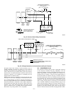
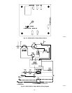
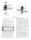
FURNACE INTERFACE
This feature provides a heat-pump lockout upon a demand for
auxiliary heat (W2) and must be used when interfacing a heat
pump with a gas/oil furnace. Field selection of the furnace-
interface option is done by connecting the factory-supplied jumper
to the ON position of the 3 terminal connectors. (See Fig. 33.)
When the option is selected, the heat pump will be locked out of
operation any time there is a thermostat demand for W2 or the
outdoor ambient is below the balance-point POT-setting selection.
(See Fig. 34.) When the unit requires defrost, auxiliary heat (W2)
energizes the furnace. After defrost is terminated, the heat pump
shuts down and the furnace satisfies the thermostat. To utilize this
function, the economic and/or thermal balance point must be
determined. See the appropriate heat pump balance-point work-
sheet available from your distributor or branch.
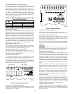
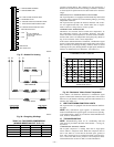
BALANCE POINT
This feature can be used in 2 different options: furnace interface or
electric-heat staging. Refer to the Furnace Interface section for its
application. If the heat pump is installed with a fan coil with
multistages of electric heat, this option can be used to stage the
banks of heat by outdoor ambient. This eliminates the need for
accessory outdoor thermostats.
When using this option to stage electric heat, first stage is
energized by a W2 demand, and second stage is energized by a W3
demand. Select the W3 desired temperature by rotating the
balance-point POT. (See Fig. 34.) Temperatures that may be
selected are 10°,15°,20°,25°,30°,35°,40°, and 45°F. The POT
is factory set at 45°F.
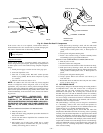
LOW-SPEED HEATING WITH AUXILIARY HEAT
If the system is operating in low-speed heating and there is a
demand for auxiliary heat (W2), the system changes to high-speed
operation. W2 is energized unless the low-voltage control wiring is
configured as described in Fig. 36.
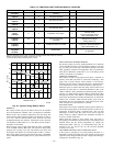
TABLE 15—FUNCTION LIGHT CODE AND DISPLAY LOCATION
CODE T’STAT UNIT DEFINITION * POSSIBLE CAUSE
Constant flash
No pause
— X
No demand
Stand by
9 —
1 flash
w/pause
— X Low-speed operation 8 —
2 flashes
w/pause
— X High-speed operation 7 —
3 flashes
w/pause
X X Ambient thermistor failure 6 —
4 flashes
w/pause
X X Coil thermistor failure 5 —
3 flashes
pause
4 flashes
X X Thermistor out of range** 4
Thermistor drift, wrong location
Incorrect wiring
Incorrect refrigerant charge
Dirty indoor/outdoor coil
5 flashes
w/pause
X‡ X
Pressure switch trip
(LM1/LM2)
3
Dirty outdoor coil
Refrigerant overcharge
Wrong indoor coil
6 flashes
w/pause†
X X Compressor PTCs out of limit 2
Low refrigerant charge
Compressor mechanical problem
Dirty indoor/outdoor coil
Constant light
No pause
No flash
X X Board failure 1
Equipment or electrical service
not grounded
*Function light signals order of importance; in case of multiple-signal request, 1 is most important.
†Signal at thermostat will occur after 3 consecutive attempted restarts and lockout has occurred.
‡Will be energized if pressure switch remains open for 1 hr.
**Check both thermistors to determine which is faulty.
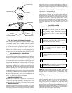
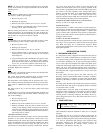
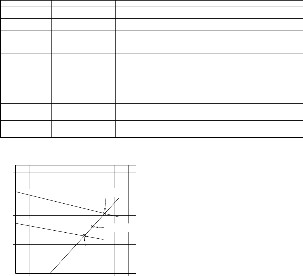
Fig. 35—Typical Cooling Balance Points
A91282
10
20
30
40
50
60
70
50 60 70 80 90 100 110 120
BTU (1000'S)
HIGH SPEED CAPACITY
HIGH SPEED
BALANCE POINT
LOW SPEED
BALANCE POINT
LOW SPEED CAPACITY
TEMPERATURE (°F)
STRUCTURE
BALANCE POINT
—32—