


pressures exceeds 500 psi. The compressor is also protected by 3
PTC devices attached to the motor windings. The PTC’s resistance
is sensed by the 2-speed control board. See Table 16 for resistance
ranges.
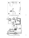
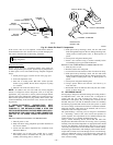
MECHANICALLY INTERLOCKED CONTACTORS
The 2-speed products are equipped with mechanically interlocked
contactors. Each contactor has interconnecting linkage, providing
independent interlocks.
The 2-speed control provides the electrical interlock. The contac-
tors are supplied with 240v coils, which reduce the va require-
ments of the low-voltage (24vac) control system.
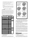
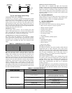
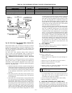
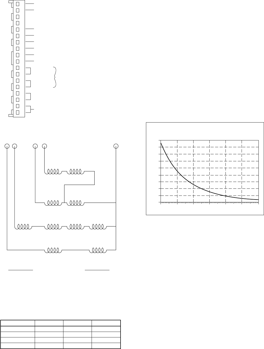
TEMPERATURE THERMISTORS
Thermistors are electronic devices which sense temperature. As
the temperature increases, the resistance decreases. Two ther-
mistors are used to sense temperature: one senses outdoor ambient,
and the other senses coil temperature (heat pump only). Refer to
Fig. 39 for resistance values versus temperature.
If the outdoor ambient thermistor should fail, a malfunction signal
appears on the indoor thermostat and 2-speed control. The control
does not initiate second-stage latching, crankcase heater is turned
on during all off-cycles, heating defaults to high speed, and defrost
initiates on demand from coil thermistor. (See Table 17.)
If the outdoor coil thermistor should fail, a malfunction signal
appears on the indoor thermostat and 2-speed control. The control
defrosts every 90 minutes of heating operation and terminates in 5
minutes. (See Table 17.)
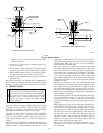
V. LED FUNCTION/MALFUNCTION LIGHTS
The 2-speed control is equipped with an LED function/ malfunc-
tion light.
NOTE: Only malfunction signal appears at thermostat. Both
function and malfunction signals appear at control board. (See Fig.
33 for LED location.) Table 15 provides the function/malfunction
code, location, and definition.
VI. TROUBLESHOOTING
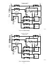
NOTE: Troubleshooting charts for air conditioning and heat
pump units are provided in the back of this manual — see Fig. 52,
53, and 54.
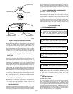
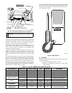
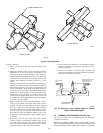
COMPRESSOR WINDING CHECK
The 2-speed compressor is nothing more than 2 single-phase
motors within 1 compressor shell. When the compressor fails to
start or run, there are 3 tests that can be made: open, ground, or
short. This compressor has no internal line-break overload; how-
ever, it does have PTC motor protectors. See Compressor PTC-
Overload Protection section for PTC overload information.
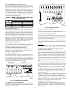
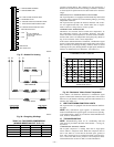
Fig. 37—Header-Pin Housing
A93576
1
2
3
4
5
6
7
8
9
10
11
12
13
14
15
16
17
18
JUMPER FOR
HEAT PUMP ONLY
C - TRANSFORMER COMMON
R - TRANSFORMER LINE
W2 - FIRST STAGE AUXILIARY HEAT
O - REVERSING VALVE
Y2 - SECOND STAGE COOLING/HEAT PUMP
L - MALFUNCTION LIGHT
Y1 - FIRST STAGE COOLING/HEAT PUMP
W3 - SECOND STAGE AUXILIARY HEAT
4 - TON
5 - TON
IF NO JUMPER IS
INSTALLED, DEFAULT
IS 3 - TON
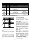
Fig. 38—Energizing Windings
A92015
T3 T8 T7 T2 T1
EXTERNAL MAIN
MAIN WINDING
4 POLE START
2 POLE START
LOW SPEED
(L1) T1
(L2) T7 + T8
HIGH SPEED
(L1) T1 + T7
(L2) T2 + T3
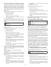
TABLE 18—TWO-SPEED COMPRESSOR
(WINDING RESISTANCE AT 70°F±2°)
WINDING 3 TON 4 TON 5 TON
T1-T2 0.80 0.70 0.60
T1-T3 3.20 2.20 1.80
T1-T7 1.30 1.00 1.00
T1-T8 3.10 2.20 2.00
Fig. 39—Resistance Values Versus Temperature
A91431
0
10
20
30
40
50
60
70
80
90
0 20 40 60 80 100 120
TEMPERATURE (DEG. F)
RESISTANCE (KOHMS)
THERMISTOR CURVE
—34—