2. Using thermocouple temperature-measuring device, route
sensor or probe underneath coil (or other convenient loca-
tion). Attach to liquid line near defrost thermostat. Insulate
for more accurate reading.
3. Turn on power to outdoor unit.
4. Restart unit in heating mode.
5. Within a few minutes, liquid-line temperature drops within
a range causing defrost thermostat contacts to close. Tem-
perature range is from 33°Fto27°F. Notice temperature at
which ohmmeter reading goes from ∞ to zero ohms.
Thermostat contacts close at this point.
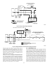
6. Remove protective cover from TP1 and TP2 speed-up
terminals, and install jumper wire on the speed-up termi-
nals.
7. Unit changes over to defrost within 90 sec (depending on
timing cycle setting). Liquid-line temperature rises to range
where defrost thermostat contacts open. Temperature range
is from 75°Fto85°F. Resistance goes from zero to ∞ when
contacts open.
8. If either opening or closing temperature does not fall within
above ranges or thermostat sticks in 1 position, replace
thermostat to ensure proper defrost operation.
CES0110063 DEFROST CONTROL
Some heat pumps built in 1991 and later incorporate a new defrost
control. The screw terminals found on the previous control board
have been replaced by a connector plug with stripped-wire leads.
This control board also contains the feature that allows the heat
pump to restart in defrost if the room thermostat is satisfied during
defrost. The board also contains a 5-minute cycle protector that
prevents the unit from short cycling after it cycles off or after a
power interruption. To troubleshoot the board, perform the follow-
ing items.
1. Turn thermostat to OFF. Shut off all power to outdoor unit.
2. Remove control-box cover for access to electrical compo-
nents and defrost-control board.
3. Disconnect defrost-thermostat leads from control board,
and connect to ohmmeter. Thermostat leads are the black,
insulated wires connected to DFT and R terminals on
control board. Resistance reading may be zero (indicating
closed-defrost thermostat), or infinity (∞ for open thermo-
stat) depending on outdoor temperature.
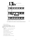
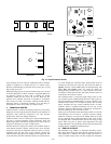
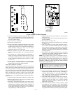
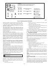
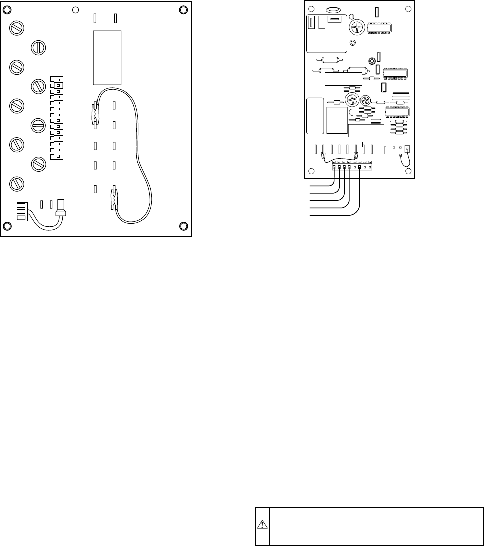
4. Jumper between DFT and R terminals on control board as
shown in Fig. 21.
5. Disconnect outdoor fan-motor lead from OF2. Tape lead to
prevent grounding.
6. Turn on power to outdoor unit.
7. Restart unit in heating mode, allowing frost to accumulate
on outdoor coil.
8. After a few minutes in heating mode, liquid-line tempera-
ture at defrost thermostat should drop below closing set
point of defrost thermostat of approximately 30°F. Check
resistance across defrost thermostat leads using ohmmeter.
Resistance of zero indicates defrost thermostat is closed and
operating properly.
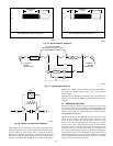
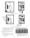
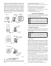
9. Short between the speed-up terminals using a thermostat
screwdriver. This reduces the timing sequence to 1/256 of
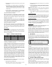
original time. (See Fig. 20 and Table 10.)
NOTE: Fig. 20 shows timing cycle set at 30 minutes; however,
for the CES30110063 board the timing cycle will be set for 90 min
and unit initiates defrost within approximately 21 sec. When you
hear the reversing valve change position, remove screwdriver
immediately. Otherwise, control will terminate normal 10-minute
defrost cycle in approximately 2 sec.
CAUTION: Exercise extreme caution when shorting
speed-up pins. If pins are accidentally shorted to other
terminals, damage to the control board will occur.
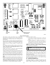
10. Unit is now operating in defrost mode. Check between C
and W2 using voltmeter as shown in Fig. 21. Reading on
voltmeter should indicate 24v. This step ensures defrost-
relay contacts have closed, energizing supplemental heat
(W2) and reversing valve solenoid (O).
11. Unit should remain in defrost no longer than 10 minutes.
Actual time in defrost depends on how quickly speed-up
jumper is removed. If it takes 2 sec. to remove speed-up
jumper after unit has switched to defrost, the unit will
switch back to heat mode.
12. After a few minutes in defrost (cooling) operation, liquid
line should be warm enough to have caused defrost-
thermostat contacts to open. Check resistance across defrost
thermostat. Ohmmeter should read infinite resistance, indi-
cating defrost thermostat has opened at approximately 80°F.
G
E
W2
14
L
W3
R
Y
O
C
W1
30
50
OF2
OF1
G
C
C
C
R
R
C
Y
O
DFT
HK32FA003/HK32FA006
A88402
OF1
OF2
O
R
T2 Y
TI
DFT
C
TEST
30
50 90
W1
O
R
W2
Y
C
CES0110063,
CES0130024
A91442
Fig. 19—Jumper DFT and R Terminals
—19—


