


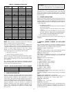
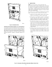
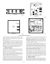
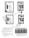
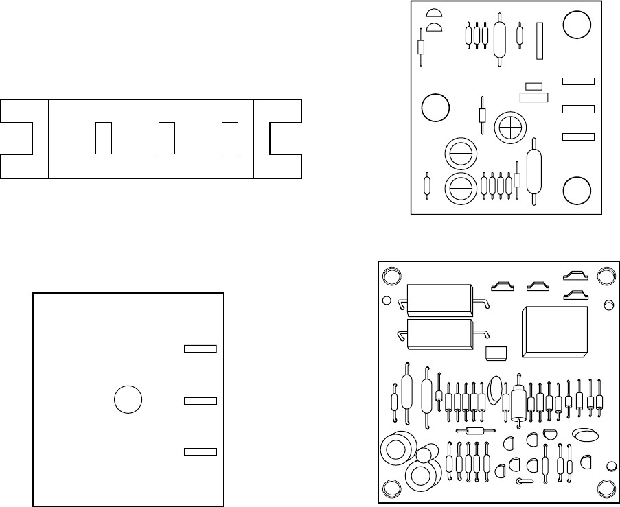
Cycle-protector device is simple to troubleshoot. Only a voltmeter
capable of reading 24v is needed. Device is in control circuit;
therefore, troubleshooting is safe with control power (24v) on and
high-voltage power off.
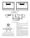
With high-voltage power off, attach voltmeter leads across T1 and
T3 and set thermostat so that Y terminal is energized. Make sure
all protective devices in series with Y terminal are closed.
Voltmeter should read 24v across T1 and T3. With 24v still
applied, move voltmeter lead from T1 terminal to T2 terminal
across T2 and T3. After5±2minutes, voltmeter should read 24v,
indicating control is functioning normally. If no time delay is
encountered or device never times out, change control.
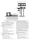
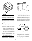
V. CRANKCASE HEATER
Crankcase heater is a device for keeping compressor oil warm. By
keeping oil warm, refrigerant does not migrate to and condense in
compressor shell when the compressor is off. This prevents
flooded starts which can damage compressor.
Crankcase heaters come in 2 basic types: wraparound-(bellyband)
type that is wrapped externally around compressor shell, and
insertion-type that is inserted into compressor oil well in shell of
compressor. Both types are used in outdoor units.
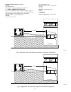
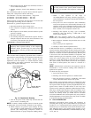
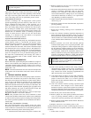
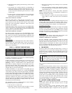
On units that have a single-pole contactor, the crankcase heater is
wired parallel with the contactor contacts and in series with the
compressor. (See Fig. 18.) When the contacts are open, a circuit is
completed from the line side of the contactor, through the
crankcase heater, through the run windings of the compressor, and
to the other side of the line. When the contacts are closed, there is
no circuit through the crankcase heater because both leads are
connected to the same side of the line. This allows the heater to
operate when the system is not calling for heating/cooling. The
heater does not operate when the system is calling for
heating/cooling. On units with 2 or 3 pole contactors, the crank-
case heater is connected to the line side of the contactor and is not
controlled by the contactor contacts.
The crankcase heater is powered by high-voltage power of unit.
Use extreme caution troubleshooting this device with power on.
The easiest method of troubleshooting is to apply voltmeter across
crankcase heater leads to see if heater has power. Do not touch
heater. Carefully feel area around crankcase heater. If warm,
crankcase heater is probably functioning. Do not rely on this
method as absolute evidence heater is functioning. If compressor
has been running, the area will still be warm.
With power off and heater leads disconnected, check across leads
with ohmmeter. Do not look for a specific resistance reading.
Check for resistance or an open circuit. Change heater if an open
circuit is detected. Some crankcase heaters in this series of units
are equipped with a crankcase-heater switch. This energy-saving
device shuts off power to heater when temperatures are high
enough that heater is not needed. Be sure this switch is functioning
normally before condemning crankcase heater.
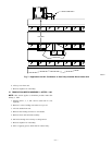
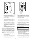
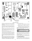
VI. TIME-DELAY RELAY
The time-delay relay (TDR) is a solid-state-controlled, recycle-
delay timer which keeps the indoor blower operating for 90 sec
after thermostat is satisfied. This delay enables the blower to
remove residual cooling in the coil after compression shutdown,
T3 T1 T2
HN67ZA002
A91438
A91439
T3
T1
HN67ZA003
T2
T3
T1
HN67ZA008
T2
A94005
T1 YEL T2 VIO
T3 BLK
T3 BLK
HN67PA025
A91440
Fig. 15—Cycle-Protector Device
—16—