


cause a rapid pressure equalization around the compressor, thus
reducing the normal shutdown sound created by reverse rotation of
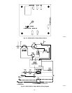
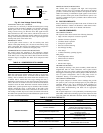
the scroll. The solenoid valve is normally closed and is wired
across high-voltage line 1 to load terminals of the contactor. (See
Fig. 18.) The solenoid-valve assembly also requires a check valve
piped in the discharge tube between the solenoid-valve tee and the
condenser coil, or reversing valve on heat pumps. The purpose of
the check valve is to prevent refrigerant from bypassing through
the solenoid valve into the suction tube when the unit cycles off.
MILLENNIUM SCROLL COMPRESSOR
I. FEATURES
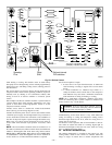
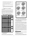
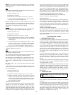
The scroll compressor pumps refrigerant through the system by the
interaction of a stationary and an orbiting scroll. (See Fig. 29.) The
scroll compressor has no dynamic suction or discharge valves, and
it is more tolerant of stresses caused by debris, liquid slugging, and
flooded starts. The Millennium scroll varies from the Copeland
scroll in that the Millennium has a shutdown flapper valve located
between the scroll plates and the discharge head, whereas the
Copeland has a check device at the discharge connection after the
discharge head. The Copeland discharge head unloads when the
compressor shuts down. The scroll plate actually runs backwards
while it unloads.A1to3second unloading of refrigerant occurs.
The Millennium flapper valve eliminates the refrigerant unloading
by not allowing the discharge head to run backwards because of its
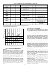
location. The Millennium scroll compressor uses Zerol 150 oil
with 3 percent Syn-O-Ad and is the only oil recommended for oil
recharge. See Table 13 for recharge requirements.
II. COMPRESSOR PROTECTION
Millennium scroll compressors are protected by an internal line-
break mounted on the motor windings. Internal protectors respond
to overcurrent and high temperature. These protectors are
automatic-reset devices containing a snap-action, bi-metal switch.
III. TROUBLESHOOTING
Troubleshooting mechanical and electrical problems in a scroll
compressor is similar to a reciprocating compressor, except that a
scroll compressor should never be allowed to pump into a vacuum.
The scroll compressor is capable of pumping into a vacuum very
quickly, which could cause fusite arcing and compressor failure.
See Step IV of Reciprocating Compressor section for removal and
replacement.
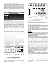
IV. SCROLL COMPRESSOR, 3–PHASE MONITOR
CES0130075 — PHASE MONITOR
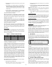
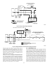
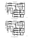
This control is factory-installed on all 3–phase, scroll compressor
models. (See Fig. 31 and 32.) On start-up, the control will energize
the pilot relay for 2 seconds. The monitor will check for correct
compressor rotation. If rotation is correct, unit will continue to run.
If rotation is incorrect, the control will break the 24vac power at
the contactor and an LED light on the control will flash. If LED is
flashing, turn off power, reverse L1 and L3 field-power leads, and
restart unit. This control will check incoming power at every
restart.
TWO-SPEED SYSTEM
I. CAUTIONS AND WARNINGS
CAUTION: For proper unit operation and reliability, the
2-speed units must be installed with the factory-supplied
balance port, hard shutoff TXV. Do not install with
indoor coils having piston or capillary-tube metering
devices.
CAUTION: Do not install equivalent interconnecting
tubing lengths greater than 100 ft. Do not decrease or
increase interconnecting tubing diameters.
CAUTION: To avoid electrical shock, bleed resistor
must be connected across run capacitor. Replace if
missing or damaged.
CAUTION: Contactor is mechanically interlocked. Do
not disable mechanical interlock. Compressor damage
may occur.
WARNING: Contactor control voltage is 240vac.
WARNING: Do not attempt to operate this equipment
below 55°F outdoor ambient temperature.
NOTE: Sections that follow describe the 598A Series B and
698A Series B products, which started production March, 1994.
For 598A Series A and 698A Series A products, refer to the
Split-System Service Manual dated 3–1–94, Catalog No. BDP
3356–115.
II. SYSTEM FUNCTIONS
COOLING OPERATION
The 2-speed products utilize a 2-stage-cooling indoor thermostat.
With a call for first-stage cooling (Y1), the outdoor fan and
low-speed compressor are energized. If low speed cannot satisfy
the cooling demand, high speed will be energized (Y1 and Y2) by
the second stage of the indoor thermostat. The thermostat has a 2°
differential between first and second stages. After second stage is
satisfied, the unit returns to low-speed operation, until first stage is
satisfied, or until second stage is again required.
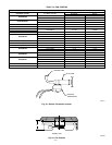
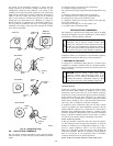
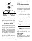
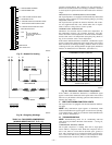
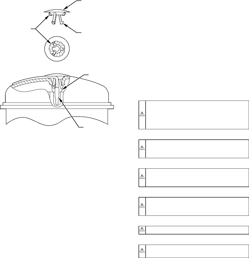
Fig. 30—Location of Discharge Thermostat
A90198
PLASTIC CAP
PRONG
BLUE SEALANT
GROMMET
THERMAL GREASE
THERMOSTAT
—29—