


6. Short between the speed-up terminals using a small, slotted
screwdriver.
7. Unit changes over to defrost within 21 sec (depending on
timing-cycle setting). Liquid-line temperature rises to range
where defrost-thermostat contacts open. Temperature range
is from 75°Fto85°F. Resistance goes from zero to ∞ when
contacts open.
8. If either opening or closing temperature does not fall within
above ranges or thermostat sticks in 1 position, replace
thermostat to ensure proper defrost operation.
CES0130024 DEFROST CONTROL
Some heat pumps built in 1993 and later incorporated a new
defrost control similar to the CES0110063 except the 5-minute
cycle protector has been removed. This control is used on heat
pump units with reciprocating compressors where short-cycle
protection is not required.
Troubleshooting this control will be the same as the CES0110063
control except for the cycle-protector function. The CES0130024
control is identical to the CES0110063 except the T2 terminal and
cycle-protector logic have been removed.
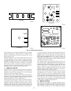
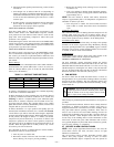
CES0130076 DEFROST CONTROL
This defrost control is the same size as the CES0130063 control
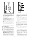
but is not backwards-compatible. (See Fig. 22.) To upgrade to the
new control, you must have replacement-defrost thermostat and
harness kit. See your replacement-component representative for kit
part number.
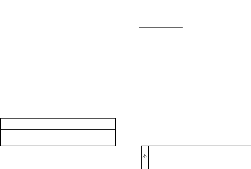
Defrost Settings
The defrost control is a time/temperature control which includes a
field-selectable time period (DIP switch 1 and 2 on board, see
Table 11) between defrost cycles of 30, 60, 90, and 120 minutes
(factory-set at 90 minutes).
To initiate a forced defrost, two options are available, depending
on the status of the defrost thermostat.
If defrost thermostat is closed, speedup pins (J1) must be shorted
by placing a Flathead screwdriver in between for 5 seconds and
releasing, to observe a complete defrost cycle. When the Quiet
Shift switch is selected, compressor will be turned off for two,
30–second intervals during this complete defrost cycle. When
Quiet Shift switch is in factory-default OFF position, a normal and
complete defrost cycle will be observed.
If defrost thermostat is in open position and speedup pins are
shorted (with a Flathead screwdriver) for 5 seconds and released,
a short defrost cycle will be observed (actual length is dependent
upon the selected Quiet Shift position). When Quiet Shift switch is
in ON position, the length of defrost is 1 minute (30 seconds
compressor-off period followed by 30 seconds of defrost with
compressor operation). On return to heat operation, compressor
will again turn off for an additional 30 seconds and the fan for 40
seconds. When the Quiet Shift is in OFF position, only a brief
30–second cycle will be observed.
If it is desirable to observe a complete defrost in warmer weather,
the thermostat must be closed as follows.
1. Turn off power to outdoor unit.
2. Disconnect outdoor fan-motor lead from OF2 on control
board. (See Fig. 22.) Tape to prevent grounding.
3. Restart unit in heating mode, allowing frost to accumulate
on outdoor coil.
4. After a few minutes in heating mode, liquid-line tempera-
ture should drop below closing point of defrost thermostat
(approximately 30° F.
NOTE: Unit will remain in defrost until defrost thermostat
reopens at approximately 80° F coil temperature at liquid line or
remainder of defrost cycle time.
5. Turn off power to outdoor unit and reconnect fan-motor
lead to OF2 on control board after above forced-defrost
cycle.
Compressor Shut Down
This control has the option of shutting down the compressor for 30
seconds while going into and out of defrost modes. This is
accomplished by turning DIP switch 3 to the ON position. See Fig.
22 for switch position. Factory default is in the OFF position.
Five-Minute Time Delay
This control has a 5–minute time delay on startup. The speedup
terminals can be used to bypass this delay. Momentary shorting
across the speedup terminals will, upon release, bypass 5–minute
time delay. Do not short out the speedup terminals for more than
5 seconds, or defrost mode will be initiated.
Troubleshooting
Troubleshooting this control is done in the same manner as the
CES0130063 control with the exceptions listed above.
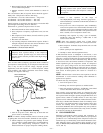
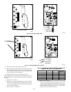
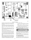
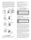
DEFROST THERMOSTAT LOCATION
On most residential, outdoor heat-pump models, the defrost
thermostat is located on the return-bend side of the coil. The 5/16
OD feeder tube from the header will enter a 1–1/2 in. to 2–in. long
3/8 OD stub prior to entering the coil. There is only one stub tube
per coil. All other feeder tubes enter the coil directly. The defrost
thermostat attaches to this stub tube. (See Fig. 23.)
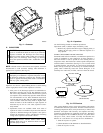
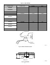
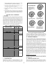
X. FAN MOTORS
Fan motor rotates the fan blade that either draws or blows air
through outdoor coil to perform heat exchange. Motors are totally
enclosed to increase reliability. This also eliminates need for rain
shield. For the correct position of the fan blade assembly, see Fig.
24 and Table 12.
WARNING: Turn off all power to unit before servicing
or replacing fan motor. Be sure unit main power switch is
turned off. Failure to do so may result in electric shock,
death, or injury from rotating fan blade.
The bearings are permanently lubricated; therefore, no oil ports are
provided.
For suspected electrical failures, check for loose or faulty electrical
connections, or defective fan-motor capacitor. Fan motor is
equipped with thermal overload device in motor windings which
may open under adverse operating conditions. Allow time for
motor to cool so device can reset. Further checking of motor can
be done with an ohmmeter. Set scale onRX1position; check for
continuity between 3 leads. Replace motors that show an open
circuit in any of the windings. Place 1 lead of ohmmeter on each
motor lead. At same time, place other ohmmeter lead on motor
case (ground). Replace any motor that shows resistance to ground,
signs of arcing, burning, or overheating.
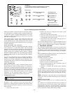
XI. SERVICE ALARM CONTROL BOARD
NOTE: If the proper night-setback thermostat is not used, the
service-alarm control will work, but there will be no light
indication on thermostat.
The service-alarm control provides immediate warning when
outdoor heat pump requires servicing. It turns on indoor
thermostat-malfunction light if compressor does not operate for
TABLE 11—DEFROST TIMER SETTINGS
SW1 SW2 SW3
On Off 30
Off On 60
Off Off 90
On On 120
—21—