


b. Route extended collector box pressure tube to relief port
connection on condensate trap.
c. Determine appropriate length, cut, and connect tube.
d. Clamp tube to prevent any condensate leakage.
C. Condensate Trap Field Drain Attachment
Refer to Condensate Drain section for recommendations and
procedures.
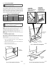
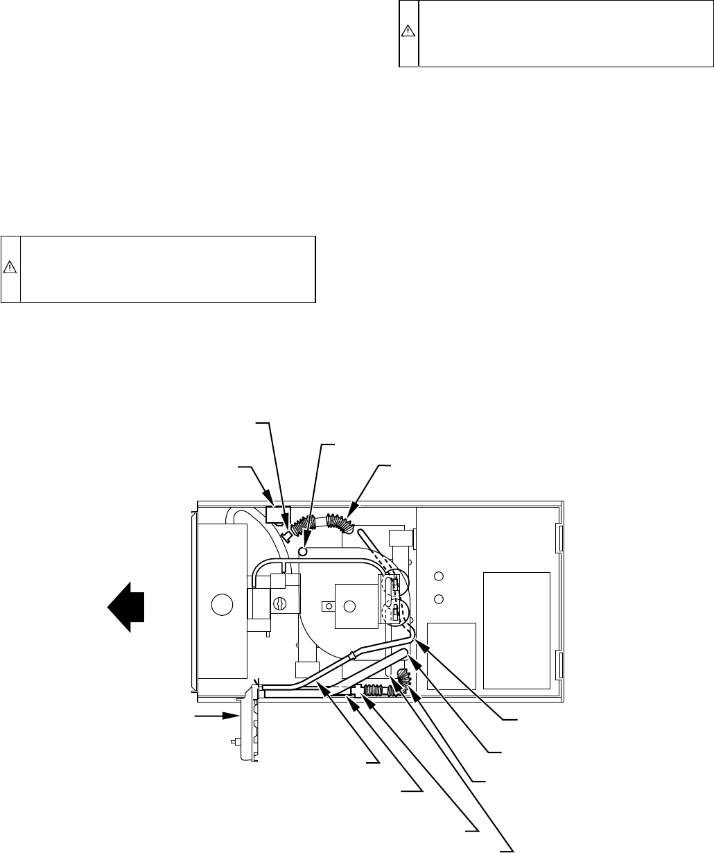
D. Pressure Switch Tubing
The LOWER collector box pressure tube (pink label) is factory
connected to the pressure switch and should not require any
modification.
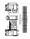
NOTE: See Fig. 9 or tube routing label on main furnace door to
check for proper connections.
E. Condensate Trap Freeze Protection
Refer to Condensate Drain Protection section for recommenda-
tions and procedures.
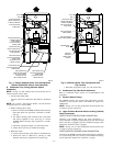
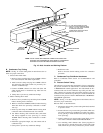
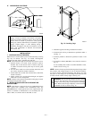
F. Construct a Working Platform
Construct working platform where all required furnace clearances
are met. (See Fig. 3 and 10.)
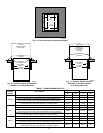
CAUTION: The condensate trap MUST be installed
below furnace. See Fig. 4 for dimensions. The drain
connection to condensate trap must also be properly
sloped to an open drain.
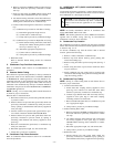
NOTE: Combustion-air and vent pipes are restricted to a mini-
mum length of 5 ft. (See Table 6.)
NOTE: A 12-in. minimum offset pipe section is recommended
with short (5 to 8 ft) vent systems. This recommendation is to
reduce excessive condensate droplets from exiting the vent pipe.
(See Fig. 10 or 29.)
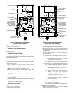
V. HORIZONTAL RIGHT (SUPPLY-AIR DISCHARGE)
APPLICATIONS
A horizontal right furnace application is where furnace blower is
located to the left of combustion and controls section of furnace,
and conditioned air is discharged to the right.
CAUTION: Local codes may require a drain pan under
entire furnace and condensate trap when a condensing
furnace is used in attic application or over a finished
ceiling.
NOTE: In Canada, installations shall be in accordance with
current NSCNGPIC Installation Codes and/or local codes.
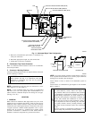
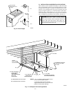
A. Condensate Trap Location
The condensate trap must be removed from the factory-installed
blower shelf location and relocated in selected application location
as shown in Fig. 2 or 11.
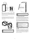
To relocate condensate trap from the blower shelf to desired
location, perform the following:
1. Remove 3 tubes connected to condensate trap.
2. Remove trap from blower shelf by gently pushing tabs
inward and rotating trap.
3. Remove casing hole filler cap from casing hole. (See Fig. 2
or 11.)
4. Install casing hole filler cap into blower shelf hole where
trap was removed.
5. Install condensate trap into casing hole by inserting tube
connection stubs through casing hole and rotating until tabs
snap into locking position.
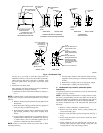
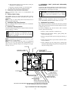
Fig. 9—Horizontal Left Tube Configuration
A93353
CONDENSATE
TRAP
AUXILIARY "J" BOX
RELOCATED HERE
PLUG
CAP
INDUCER HOUSING
DRAIN TUBE (VIOLET)
COLLECTOR BOX
DRAIN TUBE (BLUE)
COLLECTOR BOX TUBE (PINK)
RELOCATE TUBE BETWEEN BLOWER SHELF AND INDUCER HOUSING FOR
040, 060, AND 080 HEATING INPUT FURNACES
COLLECTOR BOX
EXTENSION TUBE
COLLECTOR BOX
DRAIN TUBE
(BLUE AND WHITE STRIPED)
DRAIN TUBE COUPLING
COLLECTOR BOX
TUBE (GREEN)
COLLECTOR
BOX EXTENSION
DRAIN TUBE
—9—