


SEQUENCE OF OPERATION
CAUTION: Furnace control must be grounded for
proper operation, or control will lock out. Control is
grounded through green wire routed to gas valve and
burner box screw.
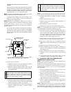
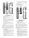
Using schematic diagram (see Fig. 24), follow sequence of
operation through different modes. This furnace has a new control
system. Read and follow wiring diagram carefully.
NOTE: If 115-v power supply to furnace or blower access panel
switch is interrupted during a call for heat, blower operates at
low-heat speed for 60 sec when power is restored before heating
cycle is resumed.
I. SELF-TEST MODE
The control center goes through a brief self-test whenever 115-v or
24-v power is interrupted. The self-test takes approximately 2 sec
to complete. After power is restored, red (microprocessor) LED
briefly comes on. Then green LED comes on for 1 sec, followed by
1 sec where both yellow and green LEDs are on. During this time,
the microprocessor is checking itself.
II. HEATING MODE
When thermostat calls for heat, R-W/W1 circuit closes.
1. Prepurge period—The inducer motor is turned on and
slowly comes up to speed. When low-pressure switch
closes, inducer motor RPM is noted by microprocessor, and
a 25 sec prepurge period begins. The RPM is used to
evaluate vent system resistance. This evaluation is then
used to determine required RPM necessary to operate
inducer in low-heat mode.
NOTE: The heat cycle can start in either high or low heat. If a
high-heat cycle is initiated, the inducer continues increasing its
speed after low-pressure switch closes. When high-pressure switch
closes, inducer motor RPM is noted by microprocessor before the
25 sec prepurge period begins. The RPM is used to evaluate vent
system resistance. This evaluation is then used to determine
required RPM necessary to operate inducer in high-heat mode.
2. Humidifier (HUM)—The HUM terminal is energized after
the inducer prepurge period is completed.
3. Ignitor warm up—At end of prepurge period, the hot
surface ignitor (HSI) is energized for a 17-sec HSI warm-up
period.
4. Ignition sequence—After HSI ignitor warm-up period is
completed, the gas valve opens, permitting gas flow to
burners where it is ignited. After 5 sec, the HSI is
de-energized, and a 2-sec flame-sensing period begins.
NOTE: The initial heat mode after 115-v or 24-v power interrup-
tion will be LOW HEAT. Low heat remains energized for 16
minutes before high heat is initiated, providing thermostat is still
calling for heat.
After initial cycle, the microprocessor evaluates the length of low-
and high-heat operating times and calculates optimum length of
low and high heat for next heat cycle. This accommodates the heat
load requirement seen as a result of thermostat operating time.
5. Flame sensing—When burner flame is sensed, the control
center holds gas valve open and begins blower on delay
period.
NOTE: Ignition sequence repeats 3 additional times before a
lockout occurs. Lockout automatically resets after 3 hr, or can be
manually reset by turning 115-v or 24-v power off (not at
thermostat) for 3 sec minimum, then turning on again.
6. Inducer speed operation—If cycle starts in low heat,
inducer speed reduces slightly after flame sense. If cycle
starts in high heat, inducer speed increases 15 sec after
flame sense. The reduction in speed in low heat is to
optimize combustion for maximum efficiency.
7. Blower on delay—The blower starts 60 sec after flame
sense if cycle started in low heat or 35 sec after flame sense
if cycle started in high heat.
NOTE: The blower starts at approximately 400-500 RPM. After
20 sec, the motor is turned off for 1/10 of a sec where a coast down
calibration is done to evaluate resistance of the conditioned air
duct system. The microprocessor then determines blower RPM
required to provide proper airflow for heating mode.
8. Electronic Air Cleaner—The EAC-1 terminal is energized
whenever the blower operates.
9. Blower off delay—When thermostat is satisfied, the
R-W/W1 signal is terminated, de-energizing gas valve
(stopping gas flow to burners), and HUM terminal is
de-energized.
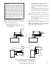
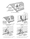
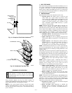
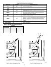
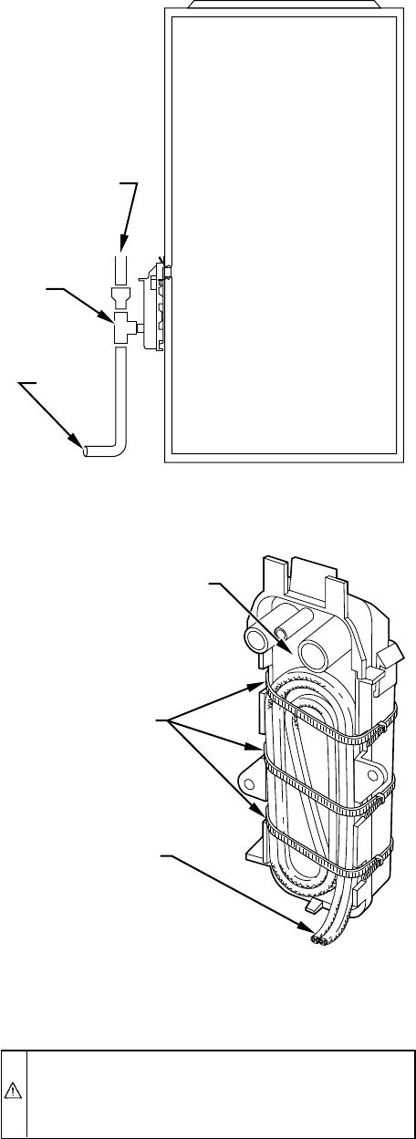
Fig. 41—Example of Field Drain Attachment
A94054
OPEN STAND
PIPE FOR
A/C OR
HUMIDIFIER
DRAIN
TEE
TO OPEN
DRAIN
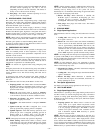
Fig. 42—Condensate Trap Heat Tape
A93036
CONDENSATE TRAP
WIRE TIE(S)
HEAT TAPE
(3 WRAPS MINIMUM)
—31—