


5. Route this extended tube (pink label) to condensate trap
relief port connection.
6. Determine appropriate length, cut, and connect tube.
7. Clamp tube to relief port connection.
E. Condensate Trap Freeze Protection
Refer to Condensate Drain Protection section for recommenda-
tions and procedures.
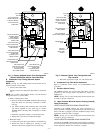
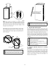
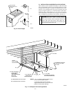
F. Construct a Working Platform
Construct working platform where all required furnace clearances
are met. (See Fig. 3 and 10.)
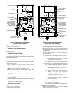
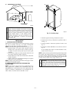
CAUTION: The condensate trap MUST be installed
below furnace. See Fig. 4 for dimensions. The drain
connection to condensate trap must also be properly
sloped to an open drain.
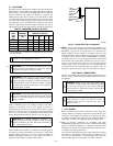
NOTE: Combustion-air and vent pipes are restricted to a mini-
mum length of 5 ft. (See Table 6.)
NOTE: A 12-in. minimum offset pipe section is recommended
with short (5 to 8 ft) vent systems. This recommendation is to
reduce excessive condensate droplets from exiting the vent pipe.
(See Fig. 10 or 29.)
LOCATION
I. GENERAL
When a furnace is installed so that supply ducts carry air to areas
outside the space containing the furnace, return air must also be
handled by ducts sealed to furnace casing. The ducts terminate
outside the space containing the furnace to ensure there will not be
a negative pressure condition within equipment room or space.
Furnace may be located in a confined space without special
provisions for dilution or ventilation air. This furnace must be
installed so electrical components are protected from water.
Locate furnace as close to center of air distribution system as
possible.
Locate furnace so combustion-air pipe lengths are not exceeded.
Refer to Table 6.
CAUTION: If these furnaces are used during construc-
tion when adhesives, sealers, and/or new carpets are
being installed, make sure all combustion and circulating
air requirements are followed. If operation of furnace is
required during construction, use clean outside air for
combustion and ventilation. Compounds of chlorine and
fluorine, when burned with combustion air, form acids
which will cause corrosion of heat exchangers. Some of
these compounds are found in paneling, dry wall adhe-
sives, paints, thinners, masonry cleaning materials, and
many other solvents commonly used in the construction
process.
Excessive exposure to contaminated combustion air will
result in safety and performance related problems.
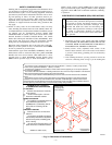
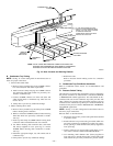
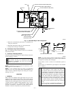
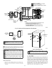
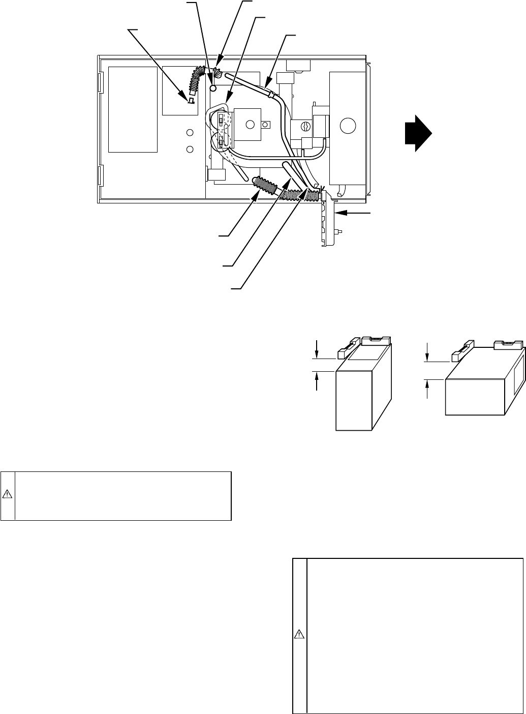
Fig. 11—Horizontal Right Tube Configuration
A93354
PLUG
COLLECTOR BOX DRAIN TUBE
(BLUE AND WHITE STRIPED)
INDUCER HOUSING
DRAIN TUBE (VIOLET)
COLLECTOR BOX
EXTENSION TUBE
COLLECTOR BOX TUBE (GREEN)
CAP
COLLECTOR BOX DRAIN TUBE (BLUE)
COLLECTOR BOX TUBE (PINK)
CONDENSATE
TRAP
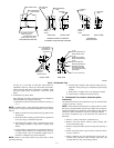
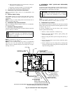
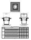
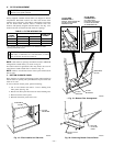
NOTE: For proper furnace operation, install furnace so that it is
level or pitched forward within 1/2 in. to ensure proper condensate
drainage from secondary heat exchangers.
A93025
UPFLOW OR DOWNFLOW HORIZONTAL
FRONT
LEVEL (0″)
TO
1
⁄2″ MAX
LEVEL (0″)
TO
1
⁄2″ MAX
FRONT
—11—