


NOTE: Do not allow insulation or other materials to accumulate
inside of pipe assembly when installing it through hole.
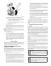
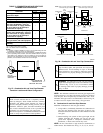
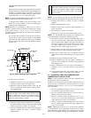
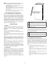
Roof terminations—Locate assembly through roof to ap-
propriate height as shown in Fig. 32.
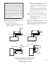
Sidewall terminations—Locate assembly through sidewall
with rain shield positioned no more than 1-in. from wall as
shown in Fig. 33.
5. Disassemble loose pipe fittings. Clean and cement using
same procedures as used for system piping.
6. Check required dimensions as shown in Fig. 32 or 33.
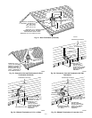
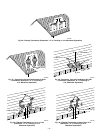
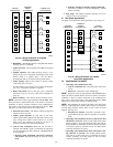
IV. MULTIVENTING AND VENT TERMINATIONS
When 2 or more 355MAV Furnaces are vented near each other,
each furnace must be individually vented. NEVER common vent
or breach vent 355MAV furnaces. When 2 or more 355MAV
furnaces are vented near each other, 2 vent terminations may be
installed as shown in Fig. 36, 37, 38, 39, or 40, but next vent
termination must be at least 36 in. away from first 2 terminations.
It is important that vent terminations be made as shown to avoid
recirculation of flue gases. Dimension "A" in Fig. 36, 37, 38, 39,
and 40 represents distance between pipes or rain shields, as
touching or 2-in. maximum separation.
CONDENSATE DRAIN
I. GENERAL
Condensate trap is shipped installed in the blower shelf and factory
connected for UPFLOW applications. Condensate trap must be
RELOCATED for use in DOWNFLOW and HORIZONTAL
applications.
Condensate trap MUST be used for all applications.
An external trap is not required when connecting the field drain to
this condensate trap.
The field drain connection (condensate trap or drain tube coupling)
is sized for 1/2-in. CPVC, 1/2-in. PVC, or 5/8-in. ID tube
connection.
Drain pipe and fittings must conform to ANSI standards and
ASTM D1785 or D2846. CPVC or PVC cement and primer must
conform to ASTM D2564 or F493. In Canada, use CSA or ULC
certified schedule 40 CPVC or PVC drain pipe, fittings, and
cement.
When a condensate pump is required, select a pump which is
approved for condensing furnace applications. To avoid conden-
sate spillage, select a pump with an overflow switch.
Furnace condensate is mildly acidic, typically in the pH range of
3.2 to 4.5. Due to corrosive nature of this condensate, a condensate
pH neutralizing filter may be desired. Check with local authorities
to determine if a pH neutralizer is required.
II. APPLICATION
The furnace, A/C, and humidifier drains may be combined and
drained together. The A/C drain must have an external, field-
supplied trap prior to the furnace drain connection. All drain
connections (furnace, A/C, or humidifier) must be terminated into
an open or vented drain as close to the respective equipment as
possible to prevent siphoning of the equipment’s drain.
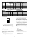
See Fig. 41 for example of possible field drain attachment using
1/2-in. CPVC or PVC tee for vent and A/C or humidifier drain
connection.
Outdoor draining of the furnace is permissible if allowed by local
codes. Caution should be taken when freezing ambient may freeze
drain pipe and prohibit draining.
WARNING: Caution should be taken to prevent drain-
ing where slippery conditions may cause personal inju-
ries. Excessive condensate draining may cause saturated
soil conditions which may result in damage to plants.
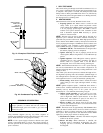
III. CONDENSATE DRAIN PROTECTION
Freezing condensate left in condensate trap and drain line may
cause cracks, and possible water damage may occur. If freeze
protection is required, use condensate freeze protection accessory
or equivalent 3 to 6 watt per ft at 120v and 40°F self-regulating,
shielded, and waterproof heat tape. See Installation Instructions
supplied with accessory or heat tape manufacturer’s recommenda-
tions.
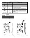
1. Fold heat tape in half and wrap on itself 3 times.
2. Locate heat tape between sides of condensate trap back.
(See Fig. 42.)
3. Use wire ties to secure heat tape in place. Wire ties can be
positioned in notches of condensate trap sides. (See Fig.
42.)
4. Wrap field drain pipe with remaining heat tape, approxi-
mately 1 wrap per ft.
5. When using field-supplied heat tape, follow heat tape
manufacturer’s instructions for all other installation guide-
lines.
CAUTION: Unit must not be installed, operated, and
then turned and left off in an unoccupied structure during
cold weather when temperature drops to 32°F or below
unless drain trap and drain line have adequate freeze
protection. See Service and Maintenance Procedures for
winterizing procedure.
A93058
32°F MINIMUM INSTALLED
AMBIENT OR FREEZE
PROTECTION REQUIRED
—29—