


NOTE: Use AWG No. 18 color-coded copper thermostat wire for
lengths up to 100 ft. For wire lengths over 100 ft, use AWG No.
16 wire.
NOTE: For 2-speed applications, refer to Sequence of Operation
section.
III. ACCESSORIES
1. Electronic Air Cleaner (EAC)
The control center EAC terminals are energized with 115v
(1.5-amp maximum) during blower operation.
a. Two extension leads are connected to the control center
EAC terminals to assist field installation of an EAC. (See
Fig. 25.) To use these leads, proceed with the following:
(1.) Strip EAC power lead insulation approximately 1/4
in.
(2.) Insert stripped end into factory-supplied black
lead’s butt connector and crimp to secure.
(3.) Strip EAC neutral lead insulation approximately 1/4
in.
(4.) Insert stripped end into factory-supplied white
leads’s butt connector and crimp to secure.
NOTE: If desired, cut butt connectors off factory leads and strip
insulation approximately 1/4 in and use field-supplied wire nuts to
connect.
b. An alternate method to attach EAC lead to control center
is the following procedure:
(1.) Remove 2 screws securing the control box to
furnace blower shelf.
(2.) Remove and discard 2 factory-supplied leads from
control center EAC terminals.
(3.) Strip EAC power leads insulation approximately
1/8 in.
NOTE: The control center EAC terminals are sized for 12 gage
maximum, solid or stranded wire.
(4.) Route EAC leads through right-hand wire grommet.
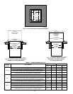
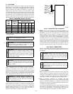
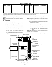
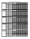
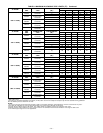
TABLE 4—ELECTRICAL DATA
UNIT
SIZE
VOLTS—
HERTZ—
PHASE
OPERATING
VOLTAGE RANGE
MAXIMUM
UNIT
AMPS
UNIT
AMPACITY†
MINIMUM
WIRE
SIZE
MAXIMUM WIRE
LENGTH (FT)‡
MAXIMUM FUSE OR
CKT BKR AMPS**
Maximum* Minimum*
042040 115—60—1 127 104 8.9 12.0 14 31 15
042060 115—60—1 127 104 8.9 12.0 14 31 15
042080 115—60—1 127 104 8.9 12.0 14 31 15
060080 115—60—1 127 104 13.8 17.9 12 32 20
060100 115—60—1 127 104 13.8 18.1 12 32 20
060120 115—60—1 127 104 11.6 15.3 12 37 20
* Permissible limits of voltage range at which unit will operate satisfactorily.
† Unit ampacity = 125 percent of largest operating component’s full load amps plus 100 percent of all other potential operating components’ (EAC, humidifier, etc.) full load
amps.
‡ Length shown is as measured 1 way along wire path between unit and service panel for maximum 2 percent voltage drop.
** Time-delay fuse is recommended.
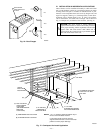
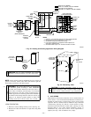
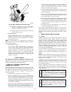
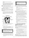
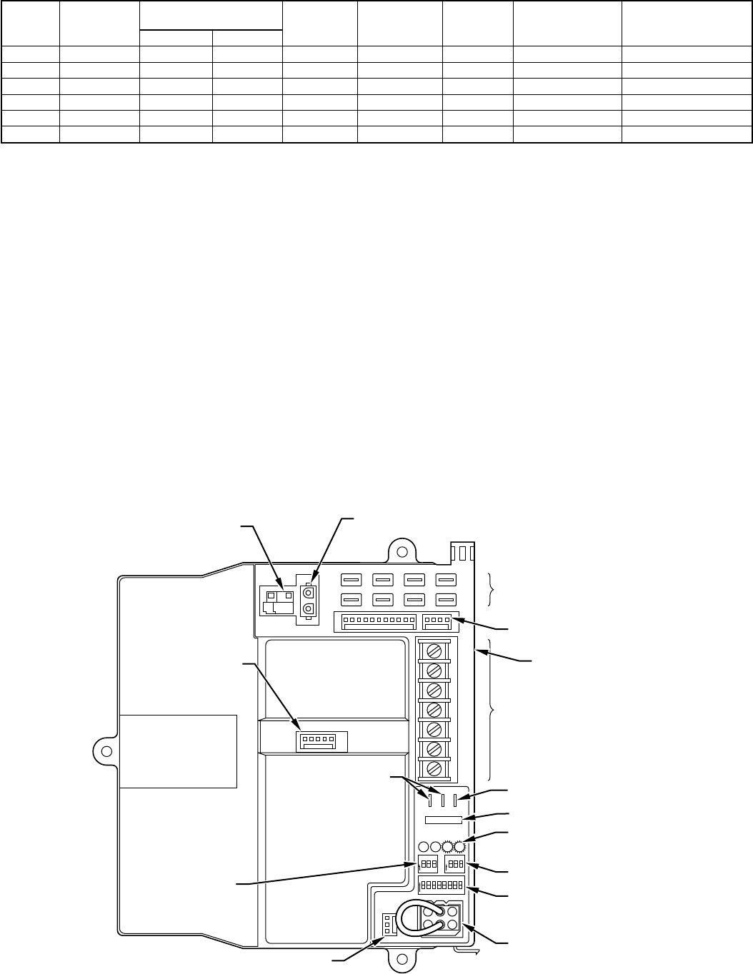
Fig. 25—Control Center
A93062
W2
COM
24V
W/W1 Y/Y2
RG
HUM
HOT SURFACE
IGNITOR CONNECTOR
EAC-ELECTRONIC AIR
CLEANER TERMINALS
(115-VAC 1 AMP MAX)
115-V
CONNECTORS
24-V THERMOSTAT
TERMINALS
PRESSURE SWITCH
CONNECTOR
HUM-HUMIDIFIER
TERMINAL
(24-VAC 0.5 AMP MAX)
TRANSFORMER
24-V CONNECTORS
3-AMP FUSE
STATUS AND DIAGNOSTIC
LED LIGHTS
AIR CONDITIONING
(A/C) SETUP SWITCH
SETUP SWITCHES
(SW) AND BLOWER
OFF DELAY SETUP
SWITCHES
MODEL PLUG
COMMUNICATION
CONNECTOR
CONTINUOUS
FAN (CF) SETUP
SWITCHES
MAIN BLOWER
CONTROL WIRE
CONNECTOR
DEHUMIDIFIER (DH)
CONNECTOR
—20—