


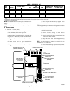
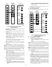
COMBUSTION-AIR INTAKE HOUSING PLUG
FITTING
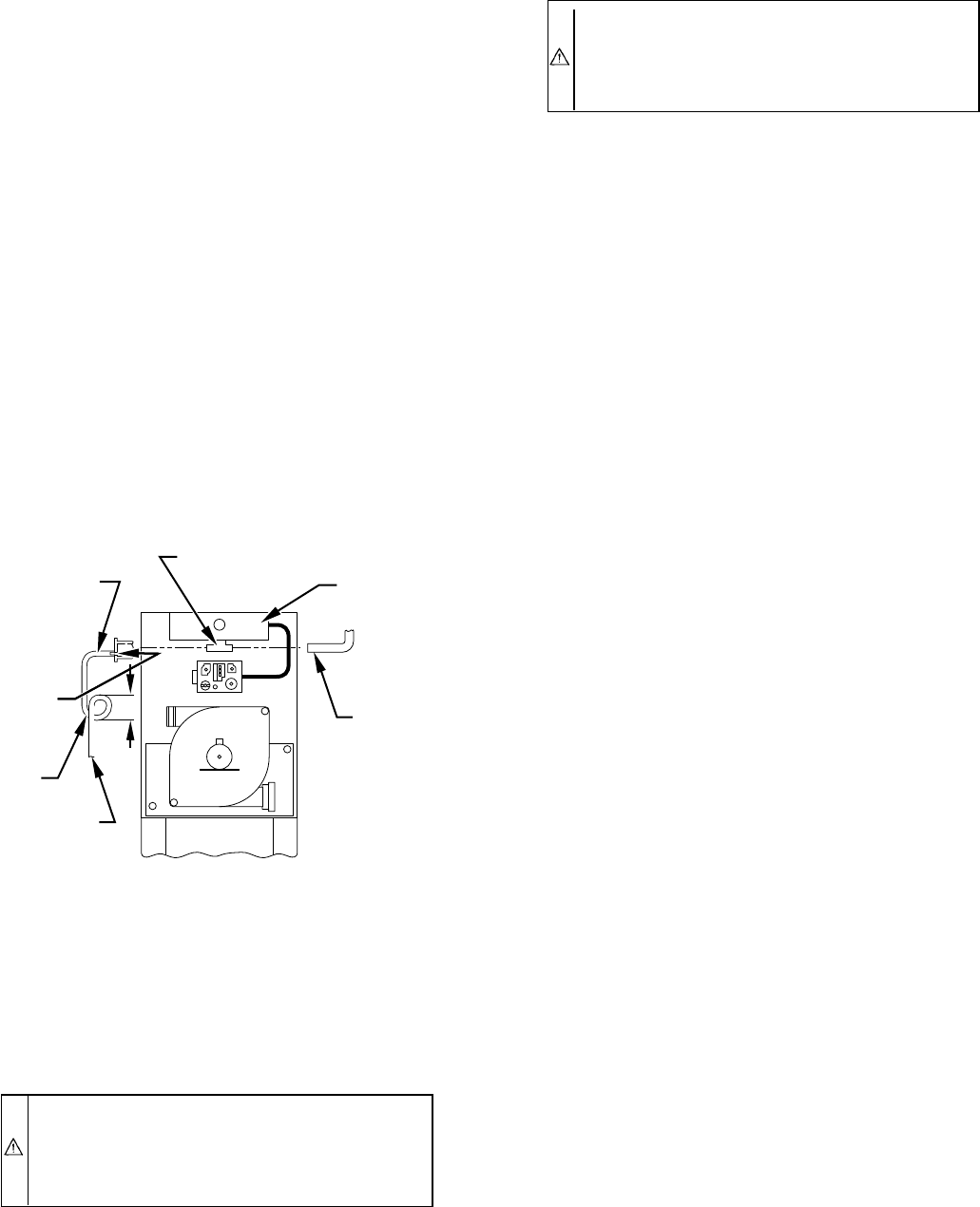
The combustion-air intake plug fitting must be installed in
unused combustion-air intake housing. This fitting must be
attached by using RTV sealant, or by drilling a 1/8-in. hole
in fitting, using hole in intake housing as a guide. Install a
field-supplied No. 6 or No. 8 sheet metal screw.
NOTE: DO NOT OVERTIGHTEN SCREW. Breakage to intake
housing or fitting may cause air leakage to occur.
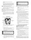
A plugged drain connection has been provided on this
fitting for use when moisture is found in combustion-air
intake pipe and combustion box.
NOTE: Moisture in combustion-air intake may be result of
improper termination. Ensure combustion-air intake pipe is similar
to that shown in Fig. 31, 32, 33, 34, or 35 so it will not be
susceptible to areas where light snow or other sources of moisture
could be pulled in.
If use of this drain connection is desired, drill out fitting’s
tap plug with a 3/16-in. drill and connect a field-supplied
3/8-in. tube. This tube should be routed to open condensate
drain for furnace and A/C (if used), and should be trapped.
(See Fig. 30.)
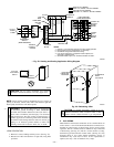
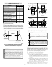
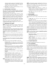
2. Attach vent pipe as follows:
a. Determine location of vent pipe connection to inducer
housing as shown in Fig. 28 for application.
b. Reposition neoprene inducer housing outlet cap and
clamp to appropriate unused inducer housing connec-
tion. Tighten clamp.
WARNING: Inducer housing outlet cap must be in-
stalled and fully seated against inducer housing. Clamp
must be tightened to prevent any condensate leakage.
Failure to follow this warning could result in electrical
shock, fire, personal injury, or death.
c. Install pipe support (factory-supplied in loose parts bag)
into selected furnace casing vent pipe hole. Pipe support
should be positioned to bottom of casing hole.
d. Insert 2-in. diameter pipe into inducer housing through
neoprene coupling and clamp in inducer housing.
Tighten clamp.
WARNING: Vent pipe must be installed and fully
seated against inducer housing. Clamp must be tightened
to prevent any condensate leakage. Failure to follow this
warning could result in electrical shock, fire, personal
injury, or death.
NOTE: A 2-in. diameter pipe must be used within the furnace
casing. Make all pipe diameter transitions outside furnace casing.
3. Working from furnace to outside, cut pipe to required
length(s).
4. Deburr inside and outside of pipe.
5. Chamfer outside edge of pipe for better distribution of
primer and cement.
6. Clean and dry all surfaces to be joined.
7. Check dry fit of pipe and mark insertion depth on pipe.
NOTE: It is recommended that all pipes be cut, prepared, and
preassembled before permanently cementing any joint.
8. After pipes have been cut and preassembled, apply gener-
ous layer of cement primer to pipe fitting socket and end of
pipe to insertion mark. Quickly apply approved cement to
end of pipe and fitting socket (over primer). Apply cement
in a light, uniform coat on inside of socket to prevent
buildup of excess cement. Apply second coat.
9. While cement is still wet, twist pipe into socket with 1/4
turn. Be sure pipe is fully inserted into fitting socket.
10. Wipe excess cement from joint. A continuous bead of
cement will be visible around perimeter of a properly made
joint.
11. Handle pipe joints carefully until cement sets.
12. Support combustion-air and vent piping a minimum of
every 5 ft (3 ft for SDR-21 or -26 PVC) using perforated
metal hanging strap.
13. Slope combustion-air and vent pipes toward furnace a
minimum of 1/4 in. per linear ft with no sags between
hangers.
14. Use appropriate methods to seal openings where vent and
combustion-air pipes pass through roof or sidewall.
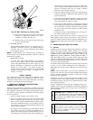
III. CONCENTRIC VENT AND COMBUSTION-AIR
TERMINATION KIT INSTALLATION
NOTE: If these instructions differ from those packaged with
termination kit, follow kit instructions.
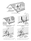
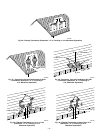
Combustion-air and vent pipes must terminate outside structure. A
factory accessory termination kit must be installed in 1 of the
installations shown in Fig. 31, 32, 33, 34, or 35. Four termination
kits are available.
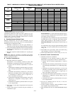
1. The 2-in. termination bracket kit is for 1-in., 1-1/2 in., and
2-in. diameter 2-pipe termination systems.
2. The 3-in. termination bracket kit is for 2-1/2 in. and 3-in.
diameter 2-pipe termination systems.
3. The 2-in. concentric vent/air termination kit is for 1-in.,
1-1/2 in., 2-in., and 2-1/2 in. diameter pipe systems when
single penetration of wall or roof is desired.
4. The 3-in. concentric vent/air termination kit is for 2-1/2 in.
and 3-in. diameter pipe systems when single penetration of
wall or roof is desired.
NOTE: Shaded parts in Fig. 31, 32, 33, 34, and 35 are considered
to be terminations. These components should NOT be counted
when determining pipe diameter. Roof termination is preferred
since it is less susceptible to damage, has reduced chances to intake
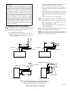
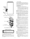
Fig. 30—Intake Housing Plug Fitting Drain
A93035
COMBUSTION –
AIR PIPE
BURNER
BOX
COMBUSTION – AIR
INTAKE HOUSING
3/8" ID TUBE
TRAP
TO OPEN
DRAIN
3/16"
DRILL
4″
MIN
—26—