


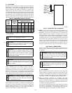
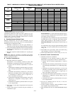
EXAMPLE:
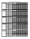
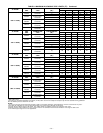
An 042080 size furnace located in Indianapolis, elevation
650 ft above sea level, could be installed in an application
requiring 3 elbows and 17 ft of vent pipe, along with 5
elbows and 16 ft of combustion-air pipe. Table 6 indicates
this application would allow a 1-1/2-in. diameter vent pipe,
but require a 2-in. diameter combustion air pipe (1-1/2-in.
pipe is good for 20 ft with 3 elbows, but only 10 ft with 5
elbows). Therefore, 2-in. diameter pipe must be used for
both vent and combustion-air pipes since larger required
diameter must always be used for both pipes. If same
installation were in Albuquerque, elevation 5250 ft above
sea level, installation would require 2-in. vent pipe and
combustion-air pipe. At 5001- to 6000-ft elevation, 1-1/2-
in. pipe is not allowed with 5 elbows, but 2-in. pipe is good
for 68 ft with 5 elbows.
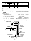
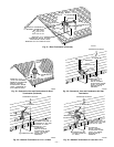
C. Combustion-Air and Vent Pipe Attachment
NOTE: All pipe joints must be watertight except attachment of
combustion-air pipe to inlet housing connection since it may be
necessary to remove pipe for servicing.
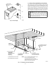
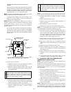
1. Attach combustion-air pipe as follows:
a. Determine location of combustion-air intake pipe con-
nection to combustion-air intake housing as shown in
Fig. 28 for application.
b. Reposition combustion-air intake housing plug fitting in
appropriate unused intake housing connection.
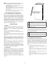
c. Insert perforated disk assembly (factory supplied) in
intake housing where combustion-air intake pipe will be
connected.
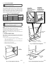
d. Install pipe support (factory-supplied in loose parts bag)
into selected furnace casing combustion-air pipe hole.
Pipe support should be positioned to bottom of casing
hole.
e. Insert 2-in. diameter pipe into intake housing.
NOTE: A 2-in. diameter pipe must be used within the furnace
casing. Make all pipe diameter transitions outside furnace casing.
f. Drill a 1/8-in. hole in 2-in. combustion-air pipe using
hole in intake housing as a guide.
g. Install a field-supplied No. 6 or No. 8 sheet metal screw
into combustion-air pipe.
NOTE: DO NOT OVERTIGHTEN SCREW. Breakage to intake
housing or fitting may cause air leakage to occur.
NOTE: Do not attach combustion-air intake pipe permanently to
combustion-air intake housing since it may be necessary to remove
pipe for service of ignitor or flame sensor.
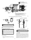
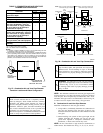
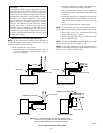
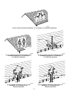
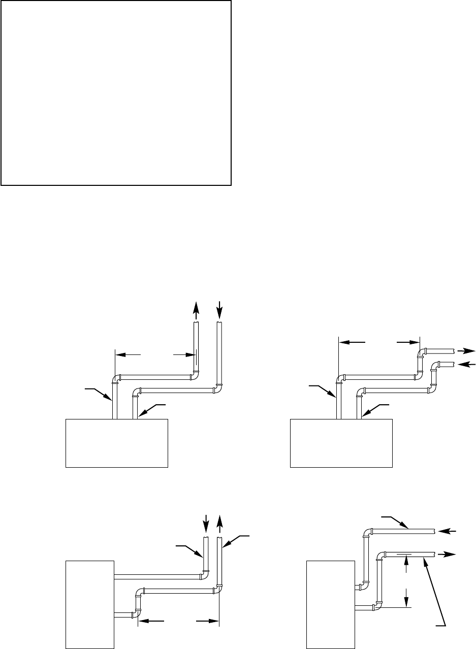
Fig. 29—Short Vent (5 to 8 Ft) System
A96230
HORIZONTAL TO ROOF HORIZONTAL TO SIDEWALL
VERTICAL TO SIDEWALLVERTICAL TO ROOF
VENT PIPE
COMBUSTION-AIR PIPE COMBUSTION-AIR PIPE
VENT PIPE
COMBUSTION-AIR PIPE
VENT PIPE
COMBUSTION-AIR PIPE
VENT PIPE
12″ MIN
12″ MIN
12″ MIN
12″ MIN
NOTE: A 12 In. minimum offset pipe section is recommended with
short (5 to 8 ft) vent systems. This recommendation is to reduce
excessive condensate droplets from exiting the vent pipe.
—23—