


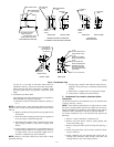
and also by a color label on each tube. These tubes are
identified as follows: collector box drain tube (blue label),
inducer housing drain tube (violet label or molded), relief
port tube (green label), and pressure switch tube (pink
label).
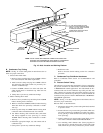
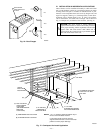
2. Condensate Trap Drain Tube
The condensate trap drain connection must be extended for
field attachment by doing the following:
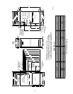
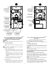
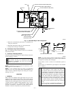
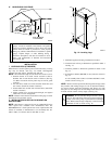
a. Determine location of field drain connection. (See Fig. 2
or 5.)
NOTE: If internal filter is used, drain tube should be located to
opposite side of casing of return duct attachment to assist in filter
removal.
b. Remove and discard casing drain hole plug button from
desired side.
c. Install drain tube coupling grommet (factory-supplied in
loose parts bag) in selected casing hole.
d. Slide drain tube coupling (factory-supplied in loose parts
bag) through grommet so long end of coupling faces
blower.
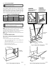
e. Cement 2 factory-supplied 1/2-in. street CPVC elbows to
rigid drain tube connection on condensate trap. (See Fig.
5.) These elbows must be cemented together and ce-
mented to condensate trap drain connection.
NOTE: Failure to use CPVC elbows may allow drain to kink,
preventing draining.
f. Connect larger diameter drain tube and clamp (factory-
supplied in loose parts bag) to condensate trap and clamp
securely.
g. Route tube to coupling and cut to appropriate length.
h. Attach tube to coupling and clamp securely.
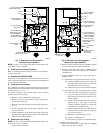
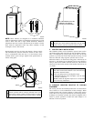
C. Condensate Trap Location (Alternate Upflow
Orientation)
An alternate location for the condensate trap is the left-hand side
of casing. (See Fig. 2 and 6.)
NOTE: If the alternate left-hand side of casing location is used,
the factory-connected drain and relief port tubes must be discon-
nected and modified for attachment. See Condensate Trap Tubing
(Alternate Upflow Orientation) section for tubing attachment.
To relocate condensate trap to the left-hand side, perform the
following:
1. Remove 3 tubes connected to condensate trap.
2. Remove trap from blower shelf by gently pushing tabs
inward and rotating trap.
3. Remove casing hole filler cap from casing hole. (See Fig. 2
or 6.)
4. Install casing hole filler cap into blower shelf hole where
trap was removed.
5. Install condensate trap into left-hand side casing hole by
inserting tube connection stubs through casing hole and
rotating until tabs snap into locking position.
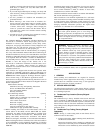
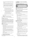
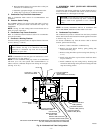
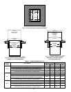
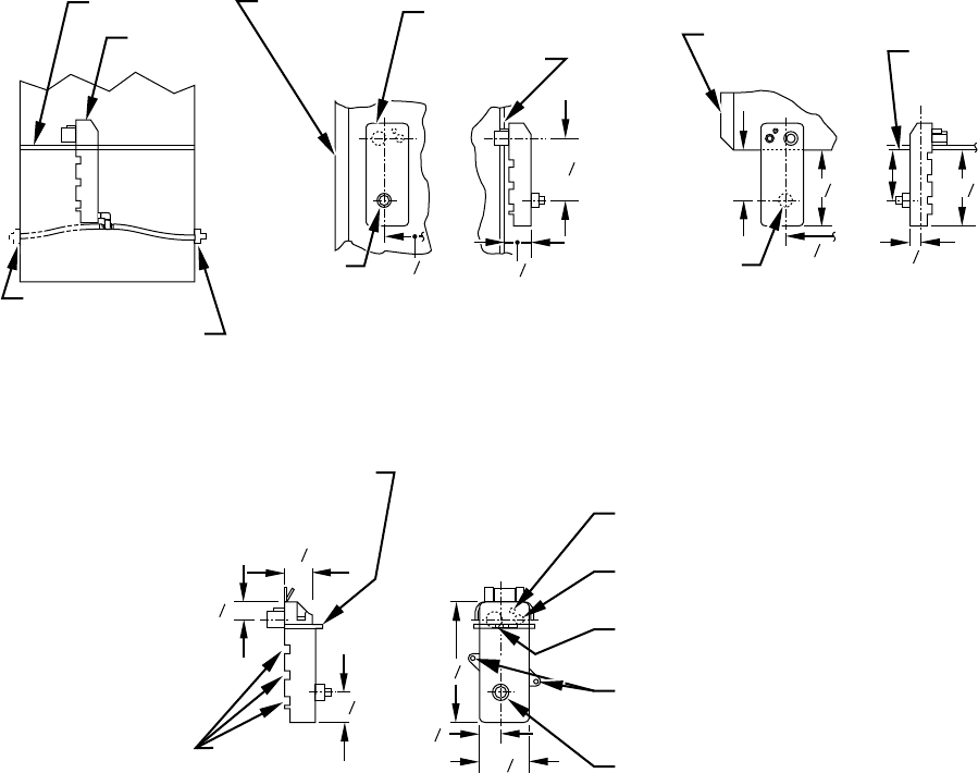
Fig. 4—Condensate Trap
A93026
1
⁄2 OD
INDUCER HOUSING
DRAIN CONNECTION
1
⁄4 OD
COLLECTOR BOX TO
TRAP RELIEF PORT
5
⁄8 OD
COLLECTOR BOX
DRAIN CONNECTION
1
⁄2-IN. PVC OR CPVC
SCREW HOLE FOR
UPFLOW OR DOWN-
FLOW APPLICATIONS
(OPTIONAL)
1
4
2
7
8
1
8
7
SLOT FOR SCREW
HORIZONTAL
APPLICATION
(OPTIONAL)
WIRE TIE
GUIDES
(WHEN USED)
1
2
1
3
4
1
3
4
FRONT VIEW SIDE VIEW
FURNACE
DOOR
FURNACE
DOOR
CONDENSATE
TRAP
7
8
1
4
26
4
FURNACE
SIDE
FURNACE
SIDE
1
2
1
1
4
26
4
3
4
5
3
4
5
4
SIDE VIEW FRONT VIEW END VIEW FRONT VIEW
3
4
DOWNFLOW AND ALTERNATE
EXTERNAL UPFLOW APPLICATIONS
HORIZONTAL
APPLICATIONS
FIELD
DRAIN
CONN
FIELD
DRAIN
CONN
CONDENSATE
TRAP (INSIDE)
BLOWER SHELF
ALTERNATE DRAIN
TUBE LOCATION
UPFLOW APPLICATIONS
CONDENSATE TRAP
DRAIN TUBE LOCATION
—5—